Kiln Main Drive Motor & Gearbox Maintenance Cement Plant
By Alex Jordan on July 8, 2026
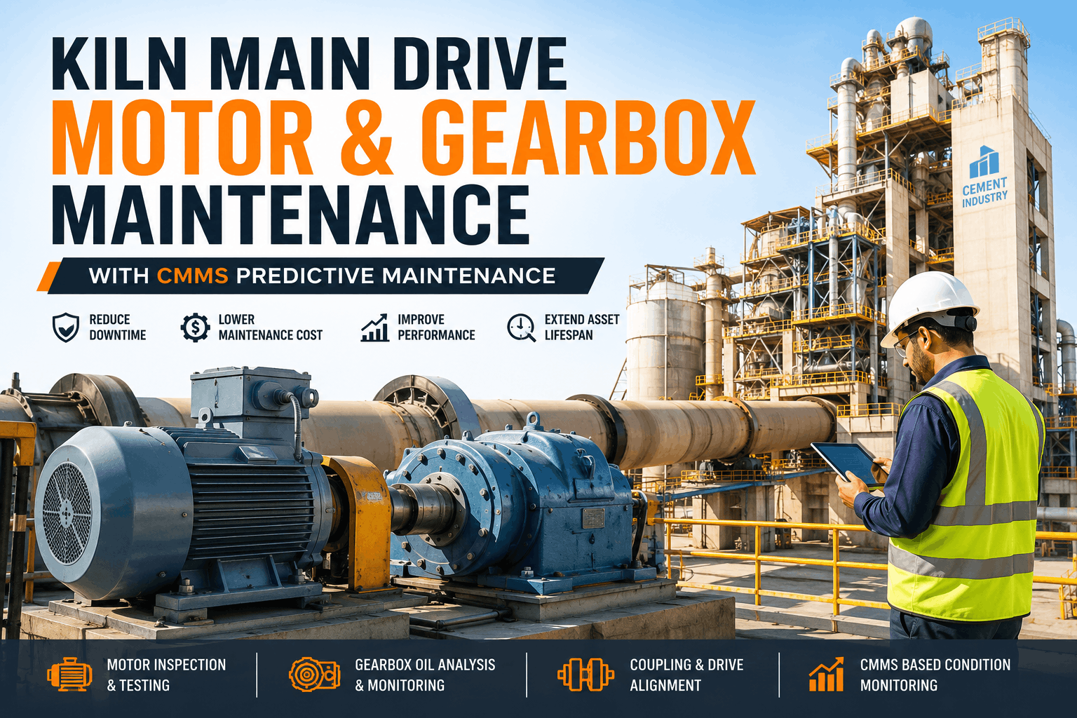
Kiln main drive system failures—encompassing the primary AC motor, gearbox, and flexible coupling—account for 19% of unscheduled cement kiln downtime, costing manufacturers $220,000–$450,000 per incident when motor burnout, gearbox oil degradation, or coupling misalignment forces kiln shutdown and equipment replacement. The drive system converts utility-frequency AC power (480V, 60 Hz in North America) into continuous kiln rotation at 2–4 RPM through a reduction gearbox (reduction ratio 150:1 to 300:1) and transmits torque through a flexible coupling to the main bearing pinion. Motor failures initiate through winding insulation degradation (caused by thermal stress from sustained overload or inadequate cooling), bearing wear (from lubrication breakdown or misalignment), or rotor imbalance (from corrosion or mechanical damage). Gearbox failures develop through oil degradation (oxidation, viscosity loss, contamination), gear tooth spalling (from misalignment or lubrication starvation), or bearing wear within the gearbox. Structured drive maintenance monitors motor winding temperature and vibration continuously, analyzes gearbox oil monthly for acid number and particle content, measures motor current draw and power factor to detect efficiency loss, inspects coupling alignment quarterly, and tracks gearbox temperature and gear tooth condition—preventing 85% of drive failures and extending equipment life 40–60% beyond nominal replacement intervals. OxMaint's kiln drive module automates motor and gearbox monitoring, coordinates lubrication scheduling, flags alignment drift before failure, and triggers predictive replacement—keeping the kiln drive system reliable and production uninterrupted.
CEMENT MANUFACTURING · DRIVE SYSTEMS · KILN MOTOR & GEARBOX · 2026
Kiln Main Drive Motor & Gearbox Maintenance: Condition Monitoring & Predictive Replacement
Kiln drive failures cost $220K–$450K per incident and halt production for 5–12 days. Deploy this protocol for motor winding temperature monitoring, gearbox oil analysis, coupling alignment tracking, efficiency trending, and CMMS-driven predictive replacement—preventing 85% of failures and extending drive life 40–60%.
19%Of unscheduled kiln downtime from main drive motor and gearbox failures in cement plants
$220K–$450KAverage cost per drive failure including equipment replacement, thermal cooling, and production loss
40–60%Extension of motor and gearbox life with predictive maintenance and optimized operational protocols
85%Reduction in drive failures with continuous condition monitoring and automated wear tracking
Kiln Drive System Architecture: Motor, Gearbox, Coupling & Load Characteristics
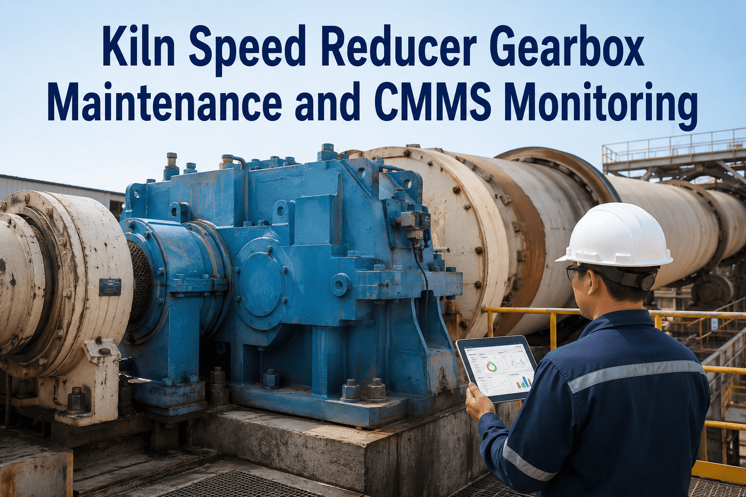
The kiln main drive system comprises four functional components operating in series. The AC induction motor (typically 300–1,200 kW, 480V, 60 Hz three-phase in North America) converts electrical energy into mechanical rotation; motors are squirrel-cage induction types with copper or aluminum rotors, stator windings rated for specific insulation classes (typically Class F or H, allowing maximum sustained winding temperatures of 155°C and 180°C respectively). The motor draws current proportional to load; a heavily loaded motor (kiln full of material or jammed rotation) draws 110–120% of rated current; an efficiently loaded motor draws 70–90% of rated current. The reduction gearbox (typically helical gear design, 150:1 to 300:1 reduction ratio) meshes motor rotation (1,000–1,200 RPM input) down to kiln rotation (2–4 RPM output); gears operate under high contact stress (>1,000 MPa on tooth flanks) and require continuous oil circulation for lubrication and cooling. The flexible coupling—typically an elastomeric jaw or disc coupling connecting the gearbox output shaft to the kiln main bearing pinion—absorbs minor misalignment (up to ±0.5 mm radial, ±1° angular) and isolates vibration. When any component degrades (motor winding insulation breaks down, gearbox oil becomes contaminated, coupling becomes misaligned), efficiency drops, temperature rises, and failure risk increases exponentially. Monitor your kiln drive system health in real-time with OxMaint's integrated motor, gearbox, and coupling monitoring dashboard.
Kiln Drive System Component Specifications & Operating Parameters
Insulation Class: F (155°C) or H (180°C). Bearings: Hydrodynamic or rolling element. Cooling: TEFC (totally enclosed fan-cooled). Thermal protection: Thermostat at 120–130°C winding temp; trips motor offline if exceeded.
Gear Type: Helical (quiet, efficient). Oil: ISO VG 220–320 circulated at 20–50 L/min. Operating temp: 45–70°C. Gear contact stress: >1,000 MPa at peak. Bearing preload critical; misalignment <±0.5 mm on input/output shafts.
Flexible Coupling
Torque Capacity: Sized to gearbox output torque | Alignment Tolerance: ±0.5 mm radial, ±1° angular
Type: Elastomeric jaw or disc. Material: Rubber (jaw) or polyurethane (disc). Lifespan: 5–10 years typical. Failure mode: Elastomer degradation or metal fatigue. Alignment monitoring: Laser alignment checks quarterly; >0.5 mm misalignment accelerates wear 3–5x.
VFD (if equipped)
Variable Frequency Drive: 0–50 Hz output | Soft-start for thermal ramp-up
Benefit: Reduces inrush current; allows gradual kiln acceleration; thermal control during cold startup. Failure mode: Capacitor bank degradation; cooling fan failure. Maintenance: Annual thermal imaging of IGBT heatsinks; filter cleaning every 6 months.
Motor Winding Temperature & Insulation Condition Monitoring
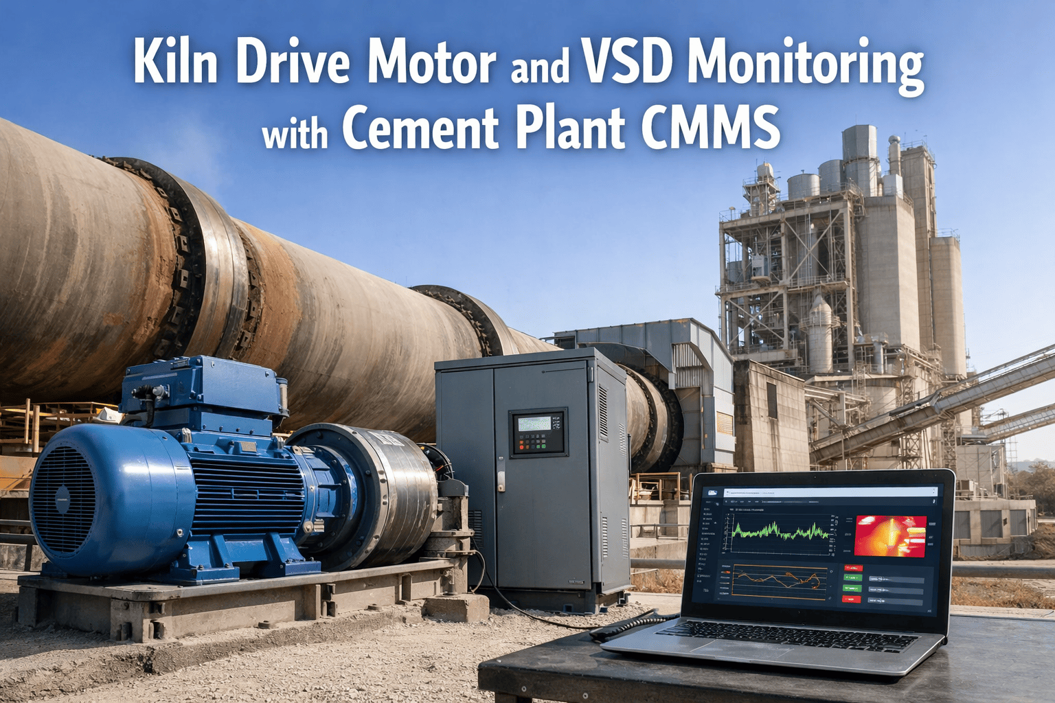
AC induction motor failure begins with insulation degradation—the breaking down of the electrical insulation surrounding copper stator windings. Insulation is rated by class (Class F at 155°C, Class H at 180°C maximum safe continuous temperature); at these temperatures, insulation materials remain flexible and provide electrical isolation. When winding temperature exceeds class rating—caused by sustained overload, inadequate cooling, or internal shorts—insulation becomes brittle, cracks develop, and electrical tracking (arcing paths) form. Once tracking initiates, phase-to-phase short circuits develop within days to weeks, causing motor burnout and complete failure. Motor winding temperature is monitored via embedded thermistors (resistance temperature detectors, RTDs) placed in motor stator slots and wired to external monitoring devices, or via infrared thermography (thermal imaging of motor housing exterior). Thermistor-based monitoring is more accurate (±2°C error margin) but requires motor connections; thermal imaging is non-invasive but measures housing temperature (which lags actual winding temperature by 5–15°C). Most industrial kilns employ both: permanent thermistors for continuous winding temperature monitoring (alert at 130°C for Class F motors, 165°C for Class H), and periodic thermal imaging (monthly) to verify external cooling airflow and detect hot spots indicating internal problems. Motor current draw is also a critical indicator: current rising >10% above baseline for a given kiln load indicates motor efficiency loss (winding resistance increasing due to temperature/insulation degradation); when current draws exceed 110% of rated current for >1 hour continuously, motor is overloaded or in early failure mode and must be de-rated or replaced. Schedule a demo to see how OxMaint integrates motor temperature, current, and thermal imaging data into predictive motor failure alerts.
Motor Condition Status Levels & Maintenance Response Actions
Winding <120°C | Current 70–90% rated
Healthy operation; stable insulation; no alarms
Action: Continue standard maintenance (monthly thermal imaging, quarterly current logging)
Winding 120–135°C | Current 90–110% rated
Elevated temperature; possible cooling restriction or modest overload
Action: Check motor cooling fan operation; verify ambient air temperature; increase monitoring to twice-monthly thermal imaging
Critical insulation stress; failure risk within weeks; urgent intervention required
Action: Reduce kiln load to <70% capacity; increase cooling (fan boost if available); schedule emergency motor replacement within 2 weeks
>150°C | Current >115% rated for >1 hour continuously
Insulation breakdown imminent; motor failure within 24–48 hours likely; shutdown mandatory
Action: IMMEDIATE KILN SHUTDOWN—Motor failure risk too high. Begin emergency motor replacement mobilization; thermal cool-down of motor (48+ hours before replacement)
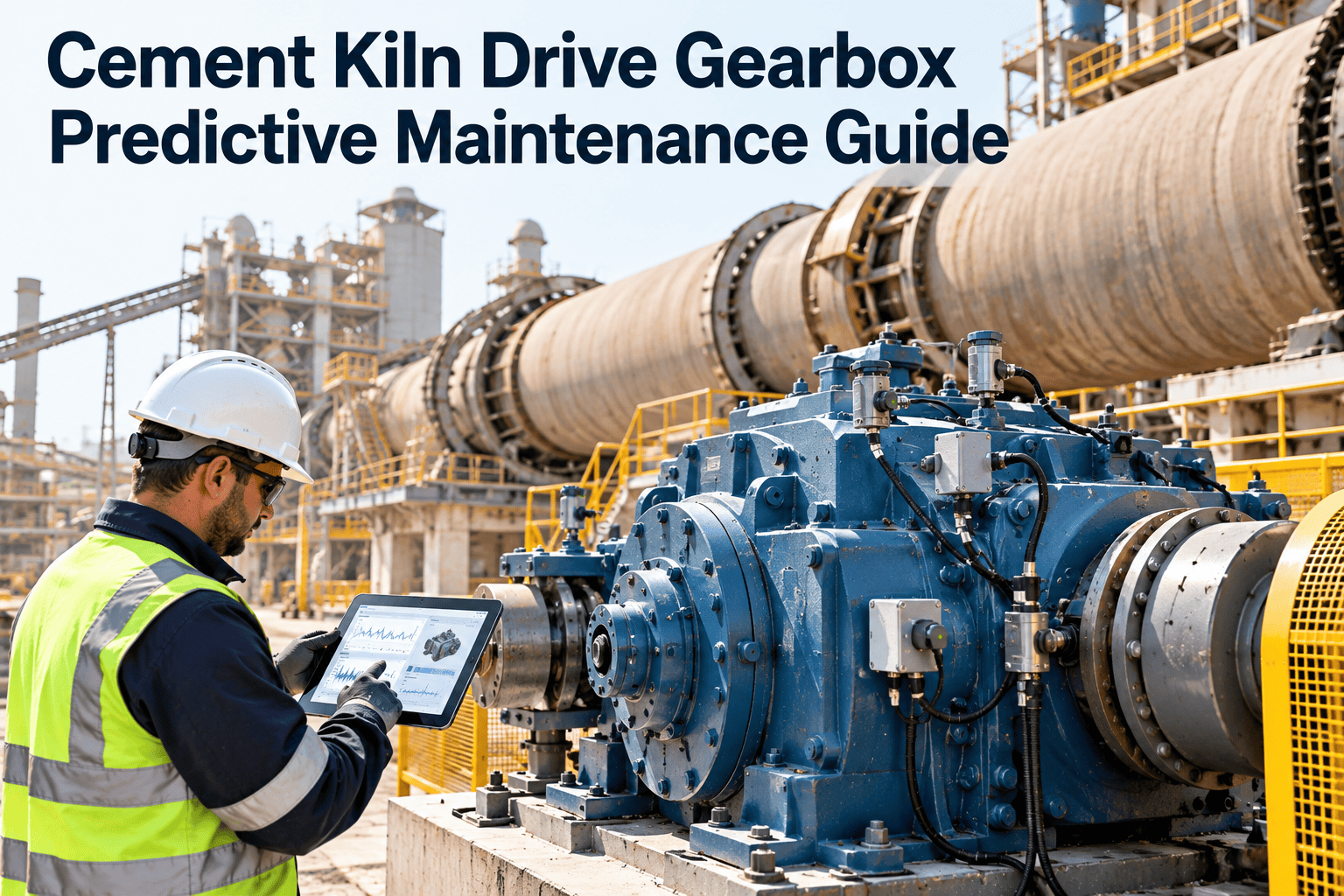
Gearbox oil performs two critical functions: lubrication (creating EHD films between meshing gear teeth and bearing races) and cooling (carrying frictional heat away from gears and bearings). When gearbox oil degrades—through oxidation, contamination with wear particles, or thermal breakdown—lubrication film thickness drops and temperature rises exponentially. Monthly oil analysis (taking a 20–30 mL sample from the gearbox sump via drain plug with sample valve) establishes the baseline and trends for: viscosity (measuring oil resistance to flow; target ISO VG 220–320 at 40°C; drift outside ±10% of specification indicates oxidation or viscosity loss), acid number (TAN, measuring oil oxidation; target <0.5 mg KOH/g for healthy oil; rising TAN indicates oxidative degradation and reduced film protection), water content (target <500 ppm; water emulsifies in oil and creates corrosive conditions), and ferrous particle count (target <300 mg/L; rising particle count indicates gear tooth wear accelerating). When oil analysis shows ferrous particles rising >300 mg/L combined with rising TAN and temperature trending upward, gear tooth spalling is likely underway and gearbox replacement should be scheduled within 4–8 weeks. Gear tooth inspection via ultrasonic thickness gauging (similar to refractory brick measurement) or magnetic particle inspection detects spalling 60–90 days before catastrophic gear tooth fracture. When multiple teeth show spalling >2 mm depth or cracks >10 mm length, gearbox must be replaced immediately or within 30 days to prevent catastrophic gear failure that can breach the gearbox housing. Start tracking your gearbox oil health with OxMaint's predictive gearbox failure modeling and automated replacement scheduling.
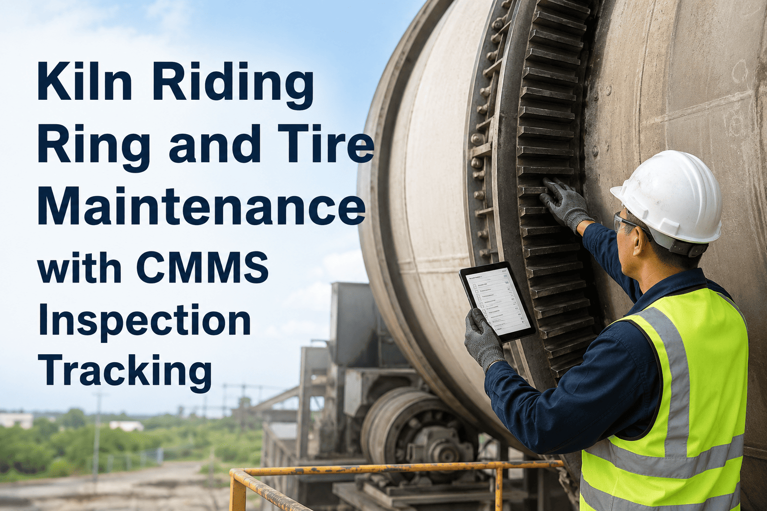
The flexible coupling connecting the gearbox output to the kiln main bearing pinion is designed to tolerate minor misalignment and absorb vibration; however, excessive misalignment accelerates coupling elastomer degradation, increases radial loads on bearing races, and induces shaft bending that can crack shafts or break keyways. Laser alignment measurement (performed quarterly using precision laser theodolites and reflective targets) compares the gearbox output shaft centerline to the kiln pinion shaft centerline; tolerance is typically ±0.5 mm radial misalignment and ±1° angular misalignment. When misalignment exceeds these tolerances—caused by bearing wear increasing clearance, shaft settling over time, or thermal growth differential—radial load on the kiln main bearing increases by 20–50% for each 0.1 mm misalignment. A coupling with 1.0 mm misalignment (twice the tolerance) imposes roughly 2–3x normal bearing load, accelerating bearing wear by 300–400% and shortening bearing life from 7 years to 2–3 years. Vibrational signature also changes with misalignment: coupling misalignment generates increased vibration at the first harmonic of kiln rotation frequency (0.05 Hz at 2 RPM = vibrations peaking every 20 seconds), whereas bearing wear generates higher-frequency vibrations. Vibration monitoring (using accelerometers mounted on the main bearing housing, typically logging 1–5 minute samples weekly) detects misalignment-induced vibration rise; when vibration amplitude exceeds baseline by >25%, coupling alignment inspection is warranted. Laser alignment correction—performed during scheduled maintenance—costs $3,000–$8,000 and takes 6–12 hours; it prevents $150,000+ in accelerated bearing wear and failure. Monitor your coupling alignment trends with OxMaint's vibration analysis and misalignment prediction alerts.
Coupling Alignment Status & Bearing Load Impact Framework
Alignment Excellent (±0.2 mm radial, ±0.5° angular)
Bearing Load: Baseline (100%)
Coupling vibration: <1 mm/s. Bearing wear: Normal baseline. Estimated coupling life: 8–10 years. Bearing life: 7–10 years.
Action: Continue monitoring quarterly; realignment only if trend shows >0.3 mm drift
Alignment Within Tolerance (±0.3–0.5 mm, ±0.8° angular)
Bearing Load: +10–20% above baseline
Coupling vibration: 1.5–2.5 mm/s. Bearing wear: Modest acceleration. Estimated coupling life: 6–8 years. Bearing life: 5–7 years.
Action: Quarterly monitoring; plan realignment within 12 months if drift continues
Alignment Degrading (±0.6–1.0 mm, ±1.5° angular)
Bearing Load: +30–50% above baseline
Coupling vibration: 3–4 mm/s (elevated). Bearing wear: Accelerating 150–200%. Estimated coupling life: 3–4 years. Bearing life: 2–4 years.
Action: URGENT—Laser alignment correction within 30 days; increase bearing monitoring to catch accelerated wear
Coupling vibration: >5 mm/s (critical, approaching ISO alarm). Shaft stress: Bending at tolerance. Bearing life: <2 years if not corrected; shaft fracture risk.
Action: IMMEDIATE—Schedule emergency laser alignment within 7 days; inspect shaft for cracks via magnetic particle inspection; prepare bearing replacement timeline
Customer Case Study: Preventive Drive Maintenance Avoided $380,000 Catastrophic Failure
"Our Plant C's Kiln 1 main motor was 10 years old (beyond the typical 10–12 year life expectancy for Class F insulation) when we installed OxMaint's drive monitoring system in early 2024. We set up continuous thermostat monitoring and monthly thermal imaging. In May 2024, our thermal images showed motor winding temperature at 138°C (normally 110°C baseline), and winding temperature was rising ~3°C per week. OxMaint's analysis predicted motor failure within 4–6 weeks if trending continued. Rather than waiting for catastrophic burnout—which would have halted production and required emergency motor replacement with extended lead times—we scheduled a planned motor replacement during our June maintenance window. We procured a 500 kW replacement motor (lead time 8 weeks, but we caught the issue early enough to coordinate delivery), arranged contractor labor, and executed the replacement over a 3-day weekend (vs. 10–14 day emergency shutdown with production loss). Planned replacement cost $95,000 (motor + labor). If we'd proceeded to catastrophic motor failure, we'd have faced emergency shutdown (1–2 weeks cooling before replacement possible), emergency motor procurement ($60K premium for expedited delivery), extended production loss (14–21 days), and potential secondary damage to gearbox (overload while operating with degraded motor efficiency). Total emergency scenario cost: $380,000+. The 4–6 week advance warning essentially prevented a $285,000+ loss." — Maintenance Director, Southwest Cement, USA
Frequently Asked Questions — Kiln Drive Motor & Gearbox Maintenance
What is the critical motor winding temperature threshold?
Class F insulation maximum safe temperature is 155°C; above 150°C, insulation degradation accelerates. Motor failure typically occurs within 2–4 weeks when winding temperature sustains above 155°C. Immediate shutdown required if >155°C is reached.
How does rising motor current indicate insulation problems?
Rising current (>110% of baseline for kiln load) indicates winding resistance increasing due to temperature damage to insulation, or developing internal short circuits. Combined with rising temperature, current >115% for >1 hour continuously predicts failure within 24–48 hours.
What gearbox oil ferrous content indicates imminent tooth failure?
Ferrous particle count >400 mg/L/month combined with rising acid number and large particle proportion indicates accelerating gear tooth spalling. Gearbox life remaining <6–12 months; replacement scheduling should begin immediately.
How does coupling misalignment affect bearing life?
Each 0.1 mm radial misalignment increases bearing load 20–50%; 1.0 mm misalignment increases bearing load 200–300%, reducing bearing life from 7 years to 2–3 years. Laser alignment correction within ±0.3 mm is critical to bearing longevity.
What is the cost difference between planned and emergency drive replacement?
Can drive system life be extended through condition-based maintenance?
Yes; monitoring motor temperature/current, maintaining gearbox oil health, and correcting coupling alignment can extend motor life 40–60% and gearbox life 35–50% beyond baseline intervals.
How does CMMS reduce drive system failure incidents?
Continuous temperature/current monitoring, monthly gearbox analysis, quarterly coupling alignment checks, and predictive modeling provide 2–12 week lead time before failure, enabling planned replacement and reducing drive failures by 85%.
Protect Your Kiln Drive System From Catastrophic Failure
OxMaint automates motor winding temperature monitoring, gearbox oil analysis tracking, coupling alignment measurement, efficiency trending, and predictive replacement scheduling across all kiln drive systems—so your cement plant gains 2–12 weeks' visibility before failure and eliminates $220K–$450K emergency drive replacements. Free to start. Secure your production with continuous, data-driven drive system management.