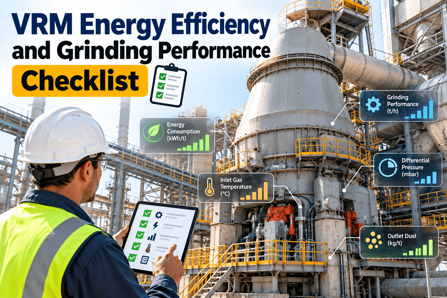
Vertical roller mills are among the more energy-efficient ways to grind raw material, cement, and slag, but they only stay efficient while their wear parts, hydraulics, airflow, and separator are in good condition. Efficiency loss is gradual, so a mill can drift upward in energy per tonne for months before anyone calls it a problem. This checklist combines maintenance and process checks so teams can protect throughput and fineness, and it can be run through cement plant maintenance management software for traceable follow-up.
VRM Energy Efficiency and Grinding Performance Checklist
Check the grinding bed, wear parts, hydraulics, airflow, and separator in a fixed order, then act on drift before it becomes lost output.
Reading the Mill: Symptoms and Likely Causes
| Symptom | Possible Causes | First Checks |
|---|---|---|
| Higher specific energy | Worn rollers or table, poor bed, false air, fan losses | Wear profile, differential pressure, damper positions |
| Rising vibration | Unstable bed, uneven feed, moisture, hydraulic fault | Bed thickness, feed stability, accumulator pressure |
| Low throughput | Restricted airflow, separator issues, worn parts | Nozzle ring, fan curve, separator speed |
| Product fineness drift | Separator wear, rotor speed, internal recirculation | Separator blades, seals, return flow |
| High reject flow | Large feed, worn nozzle ring, poor gas velocity | Reject quantity, nozzle gap, feed size |
Where Energy Is Lost
These bars show where to look and are not measured shares. Actual losses vary by mill, material, and operating setup.
Step 1: Grinding Bed and Wear Parts
- Inspect roller tyres and table segments for wear profile, cracking, spalling, and uneven wear across rollers.
- Measure wear against baseline readings, and note the gap between roller and table at the set position.
- Check hard-facing condition and weld repairs for loose or lifted layers.
- Record bed thickness, mill vibration, and motor load at stable feed, then compare with the last inspection.
- Look at the dam ring height and condition, since it influences bed depth and retention.
- Check for foreign metal or tramp material signs, such as scoring or localised damage.
- Photograph worn areas with position tags for later comparison.
Step 2: Hydraulic and Mechanical Systems
- Verify grinding pressure and accumulator pre-charge against setpoints, and look for slow pressure decay.
- Inspect hydraulic hoses, fittings, and cylinders for leaks and damage.
- Check oil cleanliness, temperature, and filter condition on both hydraulic and gearbox circuits.
- Review gearbox vibration, bearing temperatures, and lubrication flow trends.
- Inspect roller arm bearings, seals, and sealing air supply.
- Confirm that limit switches and position sensors read correctly, since false readings distort control.
Make Every Mill Round Comparable
Store readings, photos, and findings against the mill, and open work orders when drift appears.
Step 3: Airflow, Nozzle Ring, and False Air
- Inspect the nozzle ring for wear, build-up, and changes in gap or area, because these change gas velocity and material lift.
- Check differential pressure across the mill and compare with typical values for the same feed rate.
- Look for false air at inspection doors, feed gates, rotary valves, expansion joints, and duct flanges.
- Review fan damper position, speed, and power draw against output, to spot a fan working harder than before.
- Check ducts for build-up, erosion, and leaks that raise pressure loss.
- Confirm that hot gas supply and inlet temperature are stable, especially when drying moist feed.
- Inspect dust collector differential pressure and bag or filter condition where relevant.
Step 4: Separator and Product Quality
- Inspect separator blades, vanes, and cage for wear, damage, and build-up.
- Check rotor speed control and drive condition, and confirm the speed signal is correct.
- Look for leaks and worn seals that let coarse material bypass classification.
- Review fineness results against separator speed and airflow, and note any shift without a control change.
- Inspect product ducting and cyclones or filters for blockages and abnormal wear.
- Check reject handling, including conveyors and re-feed, for restrictions.
Weekly, Monthly, and Shutdown Rhythm
Before and After a Structured Efficiency Routine
- Energy drift noticed only at month-end reports
- Wear parts changed after performance drops
- Process and maintenance data kept separately
- Drift flagged by weekly trend checks
- Parts planned from measured wear
- Process and maintenance records reviewed together
Decision Path for Efficiency Drift
How Oxmaint Supports VRM Maintenance
- Inspection checklists for each step above, completed on mobile with readings and photos.
- Preventive schedules for lubrication, hydraulic checks, and wear measurement.
- Work orders for corrective action with priority, parts, and labour.
- Asset history for rollers, table segments, separator parts, and fans.
- Inventory links so wear parts are available before the planned stop.
- Dashboards showing overdue tasks and repeat issues by component.
Where your plant already records mill data, trend limits can trigger inspection tasks, which supports a condition-based approach.
KPIs for Grinding Performance
| KPI | Purpose | Review |
|---|---|---|
| Specific energy | Energy per tonne for each product type | Weekly |
| Throughput | Output against rated capacity at set fineness | Weekly |
| Wear part life | Operating hours per set of rollers and segments | Each stop |
| Mill availability | Running time against planned time | Monthly |
| Planned work share | Planned versus emergency maintenance hours | Monthly |
Frequently Asked Questions
Step 5: Feed Preparation and Material Variation
- Check feed size distribution at the mill inlet, since oversize material raises vibration and reject quantity.
- Review moisture levels in raw materials, and compare them with the drying capacity of the hot gas supply.
- Inspect feed belt weighers and feeders for accuracy and surging, because an uneven feed disturbs the grinding bed.
- Check the magnetic separator and metal detector, as tramp metal causes sudden damage to rollers and table.
- Note changes in material hardness or grindability, such as a different limestone source or clinker mix, and record them with the mill results.
- Check chutes and feed gates for wear and build-up that restrict flow or add false air.
- Review additive or gypsum dosing equipment where the mill is grinding cement, since dosing errors change mill behaviour.
Step 6: Instruments and Control Signals
- Calibrate differential pressure transmitters and check impulse lines for blockage, since a blocked line looks like a process change.
- Verify vibration sensors, bearing temperature probes, and motor current readings against a second source where possible.
- Check weigh feeder calibration and compare feed totals with production records.
- Confirm that separator speed, fan speed, and damper feedback match the real position in the field.
- Review alarm and trip settings, and confirm that nuisance alarms are not being ignored by operators.
- Compare control loop performance, because oscillating loops reduce stability and hide the true mill condition.
- Record all calibration dates and results in the asset record.
Step 7: Stops, Starts, and Safe Work Practices
- Follow the plant lock-out procedure before entering the mill, hydraulic area, or separator.
- Confirm that rollers are properly lifted and secured before any work on the table or in the mill body.
- Check gas and dust levels where confined space entry is required, and keep an attendant at the entry point.
- Inspect the mill for loose tools, debris, and removed parts before closing doors and restarting.
- Warm up gearbox and hydraulic oil as the manual advises before starting under load.
- Record start-up behaviour, including vibration and time to stable bed, since it helps explain later drift.
Roles and Review Points
| Role | Focus | Review |
|---|---|---|
| Control room operator | Stable feed, bed, vibration, and alarm response | Every shift |
| Maintenance technician | Leaks, lubrication, hydraulics, and visual wear | Daily and monthly rounds |
| Process engineer | Specific energy, fineness, and airflow trends | Weekly |
| Reliability engineer | Wear life, failure causes, and repeat defects | Each planned stop |
| Planner | Parts, labour, and stop scope for corrective work | Before each stop |
Common Mistakes That Hide Efficiency Loss
- Comparing energy figures across different products, fineness targets, or feed mixes, which makes real drift hard to see.
- Raising grinding pressure to cover for wear, which can increase vibration and shorten component life.
- Ignoring small false air leaks because each one looks minor, although together they load the fan.
- Replacing wear parts only on a fixed calendar without measuring the actual wear profile.
- Treating process alarms and maintenance findings as separate records, so patterns are missed.
- Leaving instrument calibration overdue, and making control decisions from wrong data.
Trends Shaping VRM Maintenance
- Online vibration and bearing monitoring is now common on large mills, and trend alarms support earlier inspection decisions.
- Hard-facing and in-situ repair methods extend roller and table life when they are planned around measured wear profiles.
- Control systems that stabilise the grinding bed help reduce vibration and energy use, but only when instruments are accurate.
- Plants increasingly review energy per tonne alongside maintenance records, so efficiency loss is linked to specific causes.
- Mobile inspection tools help teams capture readings and photos at the mill and share them with process engineers immediately.
Monthly Mill Walk-Down Items
Data to Record at Every Wear Measurement
- Date, operating hours, and tonnes ground since the last measurement or part change.
- Product type and fineness target during the period, as wear and energy differ by product.
- Measured profile at fixed reference points on each roller and table segment.
- Any repair carried out, including hard-facing material, welding procedure, and area covered.
- Photographs taken from the same positions each time.
- Planned and actual replacement dates, with the reason for any difference.
Questions Process and Maintenance Teams Should Ask Together
- Has specific energy changed for the same product, feed mix, and fineness, and since when?
- Did a change in operation, material, or equipment happen at the same time as the drift?
- Which inspection findings could explain the change, and have they been verified?
- What is the cost of waiting until the next planned stop, compared with an earlier corrective action?
- Who owns the follow-up, and when will the result be reviewed?
- Which findings should change the inspection routine for similar mills?
Early Warning Indicators to Trend
- Motor power divided by feed rate for a fixed product, plotted weekly, to show slow efficiency change.
- Mill differential pressure at similar feed and fan settings, which reflects bed and airflow condition.
- Vibration level at steady feed, with attention to how often it approaches the alarm limit.
- Reject quantity and reject composition, which can reveal wear, feed size problems, or airflow loss.
- Grinding pressure required to hold output, because a rising requirement can indicate wear.
- Separator motor load and speed demand at constant fineness.
- Fan power at fixed output, which helps separate airflow losses from grinding losses.
- Hydraulic accumulator pressure after standstill, to show slow gas loss.
Corrective Action Priorities
| Finding | Priority | Typical Response |
|---|---|---|
| Hydraulic leak at a roller cylinder | High | Isolate and repair before pressure loss affects the bed |
| Tramp metal damage to table segment | High | Inspect, repair or replace, and review metal detection |
| Moderate nozzle ring wear | Medium | Plan replacement or repair at the next stop |
| Small false air leak | Medium | Seal at the next opportunity and record |
| Minor hard-facing wear | Low | Monitor and measure at the next inspection |
Preparing a Planned VRM Stop
- Review wear trends and inspection findings at least several weeks ahead, and confirm which parts need replacement or repair.
- Check that rollers, table segments, nozzle ring parts, and separator parts are on site, with welding consumables where needed.
- Confirm that cranes, lifting tools, and special handling equipment are inspected and available.
- Agree contractor scope, permits, and safety arrangements before the mill stops.
- Prepare a measurement sheet so wear readings are taken at the same positions as last time.
- Plan the restart check, including hydraulic pressure, lubrication, instruments, and feed stability.
- Close the stop with a short review of what was found, what was done, and what to change next time.
Keep Grinding Efficiency From Slipping Unnoticed
Combine inspections, wear tracking, and corrective work in one maintenance record for each mill.