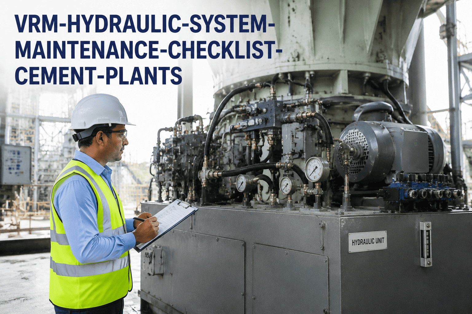
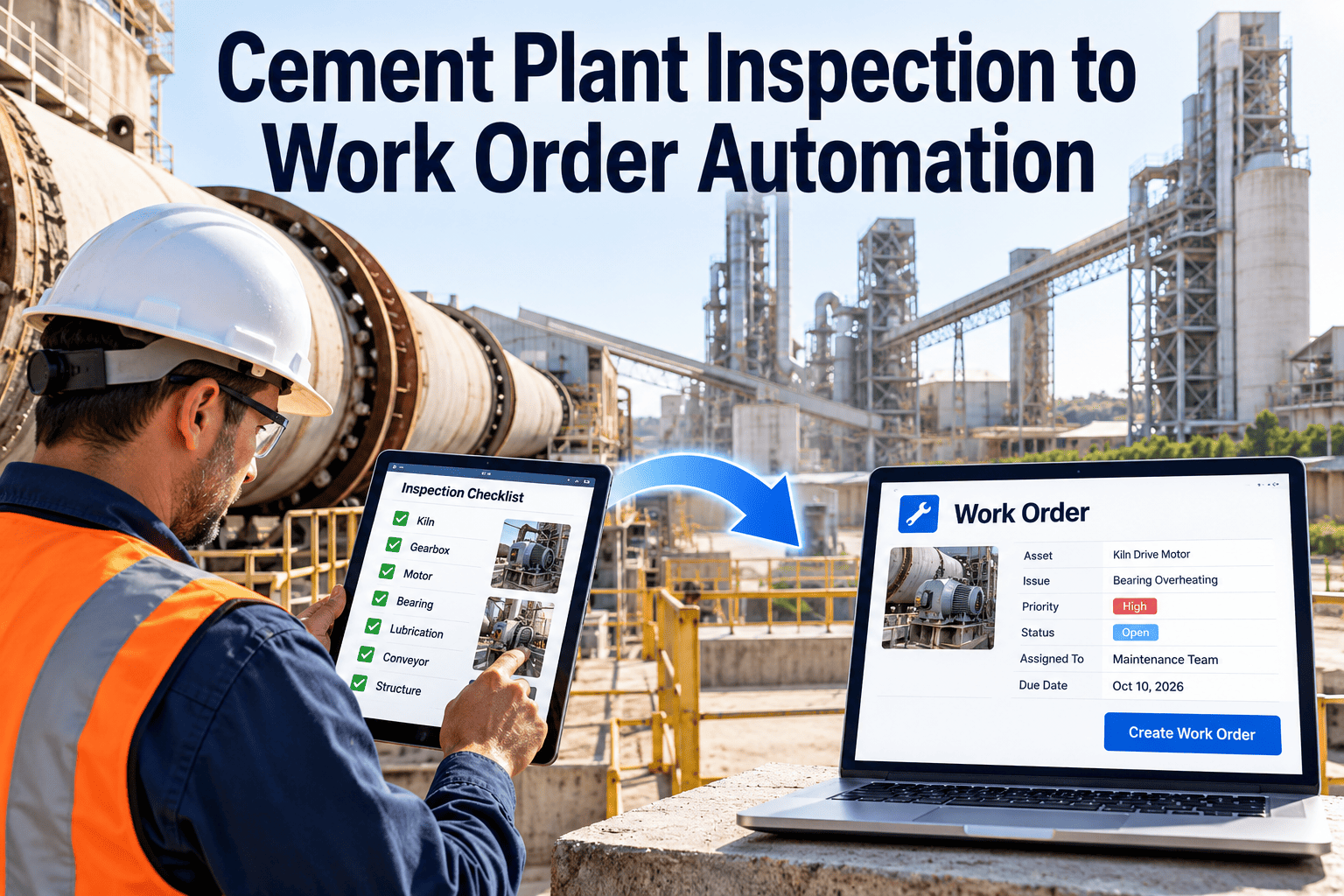
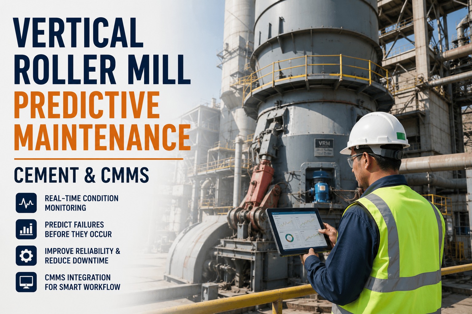
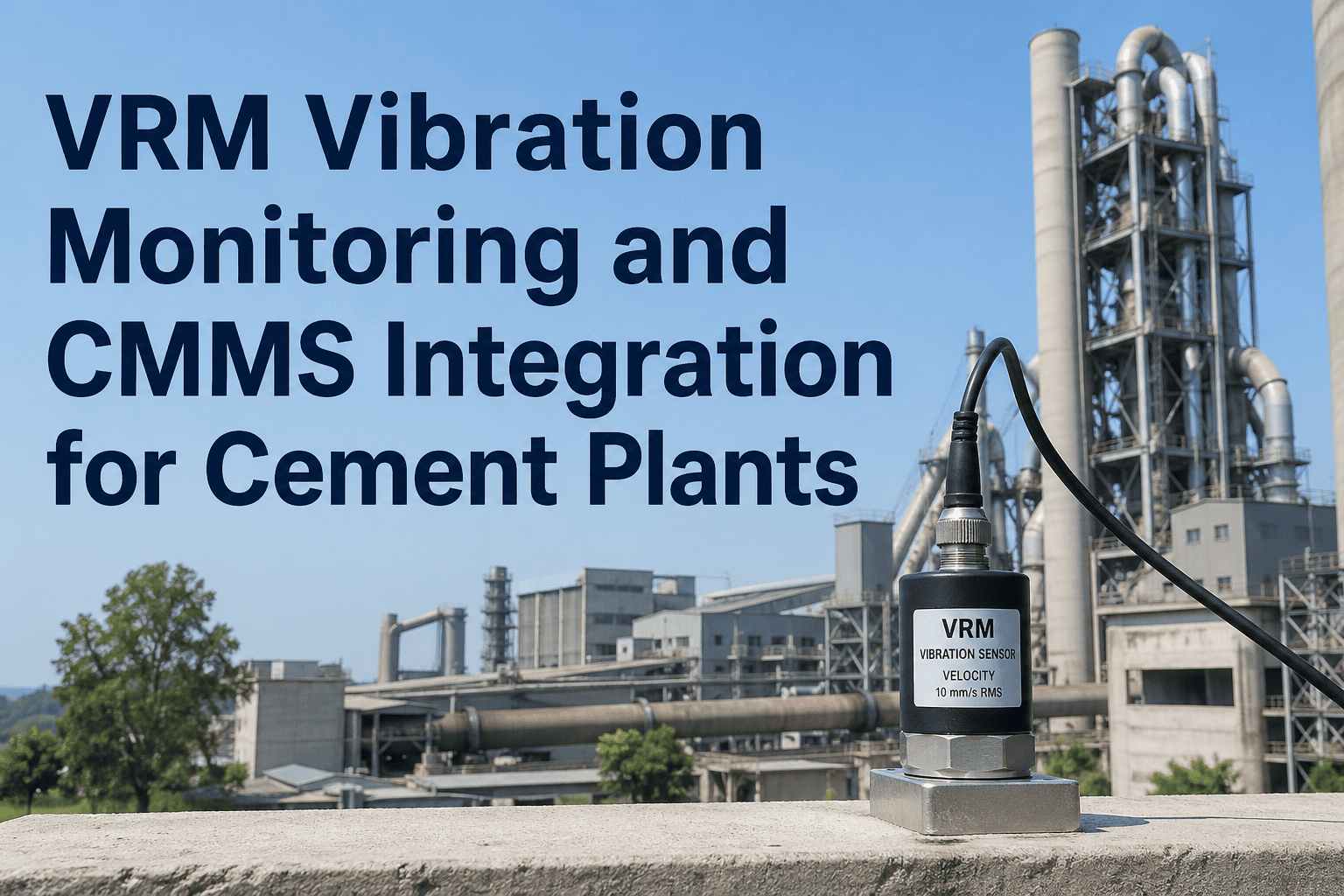
The hydraulic system on a vertical roller mill is not a support system — it is the primary grinding force. Without correct hydraulic pressure at the roller cylinders, grinding pressure drops, specific power consumption rises, and product fineness drifts from target. When the hydraulic system fails, the mill stops. Yet hydraulic maintenance at many cement plants remains one of the least-structured asset programs in the plant: oil changes happen when someone remembers, accumulator pre-charges drift for months without verification, and the first confirmed evidence of a hydraulic leak is often a housekeeping complaint rather than a maintenance work order. OxMaint Inspection Management digitizes VRM hydraulic maintenance into scheduled mobile checklists — with measurement capture, photo documentation, leak tracking, and automatic work order creation — giving your maintenance team a systematic hydraulic program that runs without reminders and creates an auditable asset record on every execution.
18–36 hrs
Average unplanned downtime per hydraulic system failure on a VRM — seal, accumulator, or pump fault
$42K
Typical cost of a VRM hydraulic pump replacement plus unplanned downtime at a 3,000 TPD plant
68%
Of VRM hydraulic failures are preventable with structured PM including oil analysis and accumulator checks
4–8 wks
Detection lead time for developing hydraulic faults when inspections include oil analysis and pressure trending
VRM Hydraulic System Architecture and Failure Zones
Understanding which components fail, why they fail, and what detection method catches each fault early is the foundation of a structured hydraulic PM program. A VRM hydraulic system has four distinct failure zones, each requiring different inspection methods and frequencies.
HP
Hydraulic Power Unit (HPU)
Pump, motor, reservoir, filters, cooler
The HPU is the source of all system failures caused by contamination, overheating, or pressure inadequacy. Oil contamination above ISO 4406 Class 18/16/13 accelerates pump wear and valve spool sticking — the two most common precursors to HPU failure. Filter bypass indicator checks and oil sampling are the primary detection tools.
Failure Impact: Full mill stop — 18–36 hrs unplanned downtime
AC
Hydraulic Accumulators
Nitrogen pre-charge, bladder or piston type
Accumulators with incorrect nitrogen pre-charge cause grinding pressure fluctuation — the mill appears to operate normally but applies inconsistent force on the rollers, producing fineness variation and increased vibration. Nitrogen pre-charge loss is a gradual failure that requires a scheduled check to detect; it produces no alarm until the accumulator is fully depressurized.
Failure Impact: Grinding instability, vibration trips, quality deviation
CY
Roller Cylinders and Seals
Tensioning and grinding force cylinders
Cylinder rod seal leaks are the most visible hydraulic fault but often go unaddressed because the leak appears minor. A cylinder losing 0.5 liters per day forces the HPU to work continuously to maintain system pressure, accelerating pump wear and contaminating the area around the roller. Early detection and seal replacement is an $800 job; continued operation leads to cylinder rod scoring and a $12,000–$28,000 repair.
Failure Impact: HPU overwork, cylinder rod damage, contamination
PV
Proportional Valves and Manifolds
Pressure control, directional, and relief valves
Proportional valve response degradation — caused by contamination, wear, or calibration drift — reduces the hydraulic system's ability to respond to mill vibration signals quickly enough to prevent resonance. This fault is typically diagnosed as a mill tuning problem rather than a hydraulic fault because it manifests as grinding instability rather than a pressure alarm.
Failure Impact: Reduced vibration damping, false mill trips, poor fineness
VRM Hydraulic System Maintenance Checklist
This checklist is structured for execution in OxMaint mobile. Measurement fields, photo capture, and pass/fail recording are built into each work order — technicians complete the check on mobile and the system builds the asset service record automatically.
Daily
Operational Monitoring Check (15 minutes)
Verify system operating pressure at the HPU gauge and at the cylinder circuit gauge
Record both values in OxMaint. A pressure drop of more than 8 bar from established operating baseline at stable mill load indicates either a developing internal leak or a filter bypass condition requiring immediate investigation
Check hydraulic oil temperature at the reservoir thermometer or temperature gauge
Record value in OxMaint. Operating temperature above 60°C accelerates oil oxidation and reduces viscosity below the minimum required for pump and valve protection. Elevated temperature on a properly cooled system indicates cooler fouling or excessive internal leakage generating heat
Inspect all visible cylinder rod surfaces for oil film, weeping, or active leak
Photograph any leakage and log in OxMaint with location and estimated severity. Distinguish between rod weeping (acceptable minimum) and active dripping (requires corrective work order). Track leak progression photo-to-photo across daily checks
Verify filter differential pressure indicator is in the green zone for all installed filter assemblies
A filter differential indicator in the red zone — even briefly during startup — indicates that the filter element is bypassing and contaminated oil is circulating in the system. This requires immediate element replacement, not next scheduled service
Check hydraulic oil reservoir level at the site glass or level indicator
A falling reservoir level with no visible external leak indicates an internal system leak — typically a cylinder seal passing oil into the mill structure. Record level reading in OxMaint daily to detect gradual level decline that indicates an internal leak not visible during external inspection
Weekly
Mechanical Inspection and Leak Survey
Inspect all hydraulic hose assemblies for abrasion, kinking, bulging, or coupling leakage
VRM hydraulic hoses operating at 200–350 bar are high-energy stored-pressure devices. Any hose showing outer braid exposure, bulging at a coupling, or weeping at a swage fitting should be scheduled for replacement at the next planned mill stop — not run to failure
Check hydraulic pump audible noise and vibration level during operation
A piston or vane pump developing internal wear produces a characteristic increase in operating noise — a rattling or knocking sound at constant speed that is distinct from normal pump tone. Record noise observation in OxMaint with severity rating. Any new noise development requires oil sample analysis within 48 hours
Inspect HPU cooling water circuit or air cooler for fouling and flow confirmation
A fouled oil cooler is the most common cause of elevated hydraulic oil temperature in cement plant environments. Verify cooling water flow at the cooler outlet or, for air-blast coolers, confirm fan operation and clean the cooler core quarterly
Verify proportional valve electrical connections and solenoid response at accessible test points
Loose or corroded solenoid connections on proportional valves cause intermittent pressure regulation failures that the process control system logs as mill vibration events rather than hydraulic faults. Check connection condition and log in OxMaint
Monthly
Accumulator Check and Oil Sampling
Verify nitrogen pre-charge pressure on all accumulators using a calibrated nitrogen charging kit
Pre-charge pressure must be verified with the hydraulic system at zero pressure — a common error is checking pre-charge with the system pressurized, which gives a false reading. Record measured pre-charge for each accumulator in OxMaint, compare to manufacturer specification, and recharge any accumulator more than 10% below specification. A consistently fast-losing accumulator requires bladder or piston seal inspection at the next planned stop
Take a representative hydraulic oil sample from the live system circulation line and submit for ISO cleanliness and viscosity analysis
A monthly oil sample is the single most cost-effective hydraulic maintenance action available. Results indicating particle count above ISO 4406 Class 18/16/13 require immediate filter element replacement and investigation of contamination source. A viscosity outside the 46 or 68 cSt grade tolerance indicates oil degradation and requires oil change scheduling. Record all results in OxMaint oil analysis module
Inspect all cylinder rod chrome surfaces for scoring, pitting, or corrosion
Cylinder rod surface damage — even minor pitting — accelerates seal wear at the rod seal location. A scored rod will destroy a replacement seal within days of installation if the rod surface is not addressed. Photograph and measure pit depth against manufacturer wear limits. Log findings in OxMaint for repair planning
Verify relief valve settings against process setpoints using a calibrated test gauge at the relief valve test point
Relief valves that have drifted above setpoint allow the system to operate at higher pressure than designed — accelerating seal wear throughout the system. Relief valves below setpoint cause the system to vent before reaching required grinding force, resulting in coarser product fineness. Record measured setting vs. specified setting in OxMaint
Planned Stop
Internal Inspection and Overhaul Tasks
Replace all hydraulic filter elements regardless of indicator condition
Differential pressure indicators detect bypass but not the total contamination load approaching bypass threshold. Planned stop element replacement maintains consistent oil cleanliness and prevents contamination events between scheduled changes. Log element condition at removal and element age in OxMaint
Inspect all cylinder rod seal assemblies — replace any seal showing extrusion, hardening, or surface cracking
Rod seal replacement at a planned stop with correct tooling and surface preparation costs $600–$1,200 per cylinder. Emergency seal replacement during an unplanned stop with scaffolding, hot work, and overtime costs $4,000–$8,000 for the same repair. The economics are unambiguous and the planned stop interval should be used without exception
Clean and inspect HPU reservoir interior — remove sludge deposits and inspect for tank coating condition
Reservoir sludge accumulation is the primary source of cold-start contamination events. Clean reservoir at every second planned stop or annually, whichever is sooner. Record sludge volume and condition in OxMaint as a leading indicator of oil degradation rate
Calibrate all proportional valves against current process setpoints using the VRM supplier's calibration procedure
Proportional valve calibration drift of 3–5% is common over 6-month service periods in high-vibration VRM environments. Recalibration restores full pressure regulation accuracy and improves mill stability — a maintenance action that directly affects product quality and specific power consumption
Deploy This Checklist on Your VRM Hydraulic System
OxMaint digitizes every tier of this checklist into scheduled mobile work orders — measurement fields, photo capture, oil analysis records, and accumulator pre-charge logs all stored per asset and available to your maintenance planner in real time.
Common VRM Hydraulic Faults: Detection and Response
| Fault Type |
Primary Detection Method |
Detection Lead Time |
Planned Repair Cost |
Unplanned Failure Cost |
| Hydraulic pump wear |
Oil particle count + noise increase |
4–8 weeks |
$8,000–$18,000 planned replacement |
$28,000–$52,000 emergency + downtime |
| Cylinder rod seal failure |
Daily rod leak inspection |
Days to 2 weeks |
$600–$1,200 planned seal change |
$4,000–$8,000 emergency repair |
| Accumulator pre-charge loss |
Monthly nitrogen check |
Detected before impact |
$80–$200 nitrogen recharge |
$6,000–$14,000 bladder replacement + downtime |
| Oil contamination above ISO limits |
Monthly oil sample analysis |
4–6 weeks before pump failure |
$800–$1,600 filter change + flush |
$28,000–$52,000 pump failure cascade |
| Proportional valve drift |
Monthly calibration check |
3–6 months gradual drift |
$400–$900 recalibration or replacement |
$3,000–$8,000 + quality deviation costs |
| Oil cooler fouling |
Daily temperature monitoring |
2–4 weeks temperature trend |
$300–$700 cleaning |
$18,000–$42,000 pump overheating failure |
Structured VRM Hydraulic Maintenance Starts Here
OxMaint connects your daily checks, monthly oil analysis, and planned stop inspections into a single hydraulic asset record — giving your maintenance team the data to predict failures, justify repairs, and document every action across every service interval.
Frequently Asked Questions
How often should VRM hydraulic oil be changed?
The correct oil change interval for a VRM hydraulic system is condition-based, not calendar-based — monthly oil sampling with ISO cleanliness and viscosity analysis is the tool that tells you when a change is actually required. A well-maintained system with clean filter elements, controlled oil temperature, and no contamination ingress can operate for 4,000–8,000 hours between full oil changes. A system experiencing filter bypasses, elevated operating temperature, or contamination events may require oil changes at 2,000 hours or less. OxMaint's oil analysis module stores all sample results per asset and triggers a change work order automatically when results breach the action threshold — replacing the guesswork of interval-based changes with data-driven timing that both extends oil life and prevents premature component wear.
What ISO cleanliness target should we maintain for a VRM hydraulic system?
For a VRM hydraulic system operating with proportional control valves and high-pressure piston pumps, the target oil cleanliness is ISO 4406 Class 17/15/12 or better. Many VRM hydraulic systems in cement plants are found operating at Class 20/18/15 or worse — two to three cleanliness classes above target — because filter change intervals are too long and contamination ingress through cylinder seals and reservoir breathers is not controlled. At ISO Class 20/18/15, pump component life is reduced to 20–30% of its designed service life compared to operation at the target cleanliness level. Each cleanliness class improvement doubles the expected service life of precision hydraulic components. The monthly oil sample program included in the OxMaint checklist above is the only reliable method for tracking whether your system is operating within the target cleanliness band between full filter changes.
How does OxMaint handle oil analysis data from external laboratories?
OxMaint's inspection management module supports manual entry of oil analysis results with full parameter recording — ISO particle count class, viscosity at 40°C, water content, TAN, TBN, and metal particle levels including iron, copper, and silicon. Analysis results are stored against the specific asset and work order that generated the sample, creating a longitudinal database of oil condition per VRM. When results exceed the configured action thresholds, OxMaint automatically creates a corrective work order for the appropriate response — filter change, oil change, or investigation of contamination source. For laboratories with digital report formats, results can be imported directly into OxMaint via CSV, eliminating manual transcription errors and ensuring no analysis result is recorded in a paper file that maintenance planners cannot access.
Can we use OxMaint to manage hydraulic maintenance across multiple VRMs at a multi-plant operation?
Yes. OxMaint manages multi-site asset hierarchies, so all VRM hydraulic systems across all plants in your portfolio are accessible from a single platform with plant-level and asset-level drill-down. The maintenance planner at each plant manages their own VRM hydraulic work orders, while the corporate reliability team has visibility into aggregate PM compliance, open corrective work orders, and oil analysis trends across all sites. This structure allows a corporate reliability engineer to identify, for example, that two plants are consistently reporting elevated iron particle counts in their VRM hydraulic oil — a pattern suggesting a common contamination issue worth investigating across the portfolio — while plant-level planners focus on executing the day-to-day inspection and repair workflow. OxMaint's multi-site capability is designed for exactly this distributed maintenance management structure.
What are the most important differences between maintaining a Loesche VRM hydraulic system and an FLSmidth ATOX hydraulic system?
While the fundamental hydraulic principles are identical, the accumulator configuration, cylinder arrangement, and proportional valve system differ between major VRM suppliers in ways that affect the inspection priorities in this checklist. Loesche mills typically use a master and slave cylinder arrangement per roller with individual accumulator banks, meaning accumulator pre-charge checks must be conducted per cylinder pair rather than per system. FLSmidth ATOX mills use a single hydraulic cylinder per roller with a common accumulator circuit, simplifying pre-charge verification but requiring higher attention to the central proportional valve block response. Pfeiffer MPS series mills use a hydropneumatic spring system that has different accumulator pre-charge specifications and a more sensitive dependency on correct nitrogen charge than standard cylinder systems. OxMaint checklist templates can be customized per mill type and per VRM supplier specification — your maintenance team builds the checklist once, and every subsequent execution follows the exact procedure for your specific equipment design.