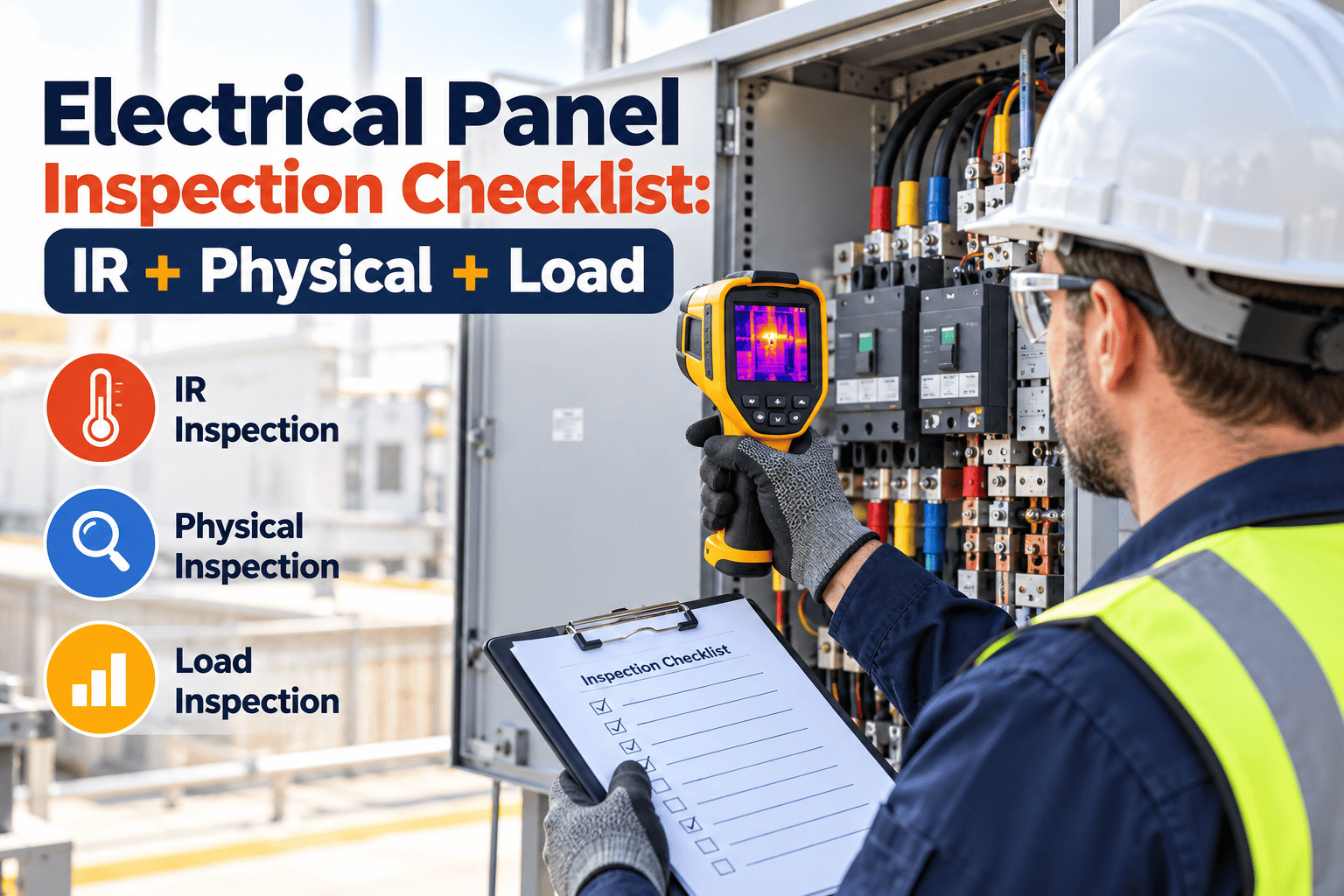
Electrical panels rarely fail without warning, but the warning is usually invisible: a connection running a few degrees hotter than its neighbours, a breaker carrying more load than its rating allows, or a terminal that has slowly loosened under thermal cycling. A complete panel inspection combines infrared thermography, a physical inspection, and load analysis so each method covers the blind spots of the others. This checklist shows how to run all three and record the results in a maintenance management platform for trending and follow-up.
Electrical Panel Inspection Checklist: IR, Physical and Load
Scan for hot connections, inspect the enclosure and components, and measure real loading on facility panels. Together these three checks find loose terminations, overloaded circuits, and aging gear before they cause an outage or fire.
Inspection Record Header
Safety Gate: Do Not Skip This Step
Qualified persons only
Opening energized panels and taking measurements must be done by qualified personnel following NFPA 70E and your site electrical safety program.Know the hazard
Review arc flash labels, incident energy, approach boundaries, and the required PPE before any cover is removed.Use the right method
Where available, IR windows or ports allow scanning without opening live equipment and can reduce exposure.Plan the outage separately
Torque checks and cleaning that require removing covers or touching terminals need a de-energized work plan with lockout and tagout.- Confirm a job briefing has been held, emergency contacts are known, and a second qualified person is present where policy requires it.
- Coordinate with operations so critical equipment is not affected by scheduling, and so panel loads are representative of normal operation.
- Stop work and report any damaged, hot, noisy, or discoloured gear as an urgent corrective action instead of continuing the checklist.
Why Standards Now Push Toward Structured Programs
- NFPA 70B covers electrical equipment maintenance. Its 2023 edition became a standard rather than a recommended practice and calls for an electrical maintenance program with defined procedures, condition assessment, and records.
- NFPA 70E addresses electrical safety in the workplace, including arc flash and shock protection during inspection and testing.
- NETA maintenance testing specifications are widely used for test methods and for evaluating infrared findings.
- NEC requirements such as working clearance, labeling, and panel directories also affect what inspectors should verify.
Check which editions your jurisdiction, insurer, and corporate standards apply, because requirements and intervals can differ between sites.
Pre-Inspection Preparation Checklist
- Pull the one-line diagram, panel schedules, and the last inspection report for each panel on the route
- Review the arc flash study date and confirm labels match the current electrical system configuration
- Confirm camera, clamp meter, and torque tool calibration dates are current
- Check that PPE is rated for the incident energy shown on each panel label
- Notify operations, security, and any tenants about work that could affect power or alarms
- Identify panels with IR windows and those that require covers to be removed
- Verify access to locked electrical rooms, keys, and elevators before the scheduled day
- Prepare a route that scans higher-load panels during normal peak operating periods
- Load open deficiencies from previous scans so repairs can be verified, not rediscovered
Stage 1: Infrared Thermography
Scan Preparation
- 1Confirm loading. Scan when equipment carries meaningful load, since many industry guidelines recommend at least 40 percent of rated load and higher loading gives more reliable results.
- 2Use a suitable camera. Check calibration status, resolution, and ability to focus at the required distance.
- 3Set emissivity and reflected temperature. Bare copper, shiny lugs, and insulated conductors read differently, so correct settings or use reference tape where appropriate.
- 4Scan every component. Include main lugs, breakers, bus connections, neutral and ground bars, fuses, disconnects, and feeders.
- 5Compare similar components. Compare phase to phase and breaker to breaker, since an abnormal rise is easier to see against similar loads.
- 6Capture paired images. Save the thermal and visible image, with load current and ambient temperature, for the report.
Severity Guide Based on Similar-Component Temperature Rise
| Temperature rise vs similar component | Typical classification | Typical response |
|---|---|---|
| 1 to 3 degrees C | Possible deficiency | Note and monitor, recheck on next scan |
| 4 to 15 degrees C | Probable deficiency | Schedule repair at the next planned outage |
| Above 15 degrees C | Major discrepancy | Repair promptly under a controlled plan |
| Any condition with visible damage, odor, or arcing signs | Immediate hazard | Escalate immediately and follow site emergency procedures |
These bands follow commonly used NETA-style guidance. Your own program, insurer, or equipment manufacturer may use different criteria, so write the thresholds you apply into the program.
Stage 2: Physical Inspection Checklist
- Working spaceCheck: Clear access in front of the panel, with working clearance maintained and no storage, shelving, or equipment in the zoneIf found: Remove obstructions and correct layout
- EnclosureCheck: Correct rating for the environment, doors close and latch, knockouts sealed, no rust, dents, or water entryIf found: Repair, replace covers, and seal openings
- Labels and directoryCheck: Panel name, voltage, source, arc flash label, and a legible circuit directory that matches actual loadsIf found: Update and relabel after verifying circuits
- Dead front and coversCheck: All covers, blanks, and barriers present, with correct screws and no open spacesIf found: Install missing parts immediately
- ConductorsCheck: No overheated insulation, discoloration, nicks, double-lugging, or damaged strandsIf found: Escalate for repair under a controlled outage
- TerminationsCheck: No signs of overheating, corrosion, pitting, or loose hardware on lugs and busbarsIf found: Plan de-energized cleaning and torque to specification
- BreakersCheck: Correct type and rating, no cracked cases, no discoloration, proper handle operation, and trip indicatorsIf found: Replace damaged units and document the cause of any trip
- Grounding and bondingCheck: Ground and neutral bars properly separated or bonded as required, with secure connectionsIf found: Correct by a qualified electrician
- EnvironmentCheck: Dust, moisture, vermin, corrosive vapors, excessive heat, or vibration near the panelIf found: Clean, seal, ventilate, or relocate sources
- Spare capacityCheck: Available spaces and spare breakers recorded for future load planningIf found: Record and flag panels near capacity
De-Energized Follow-Up: Cleaning, Torque, and Repair
- 1Plan the outage. Identify affected loads, backup options, switching sequence, and the shortest safe window, with operations approving the schedule.
- 2Lock out and verify. Apply lockout and tagout, test for absence of voltage with a verified meter, and apply grounding where required.
- 3Inspect closely. With power off, look for burned insulation, pitted contact surfaces, cracked busbar supports, and signs of tracking.
- 4Clean and torque. Clean contact surfaces as the manufacturer allows, and tighten connections using a calibrated torque tool to published values.
- 5Restore and rescan. Re-energize under the approved procedure, then repeat the IR scan under load to confirm the repair worked.
Turn Panel Findings Into Tracked Work
Schedule IR scans, capture images and readings, and create a work order for every hot spot or physical deficiency.
Stage 3: Load Analysis
- Measure phase currents at the main and at major branch circuits using a calibrated clamp meter or power logger.
- Compare with ratings. Divide measured current by breaker or feeder rating. Continuous loads are generally limited to 80 percent of the overcurrent device rating unless the device is rated for continuous operation at 100 percent.
- Check phase balance. Large differences between phases can cause overheating and wasted capacity, and many programs investigate imbalance above about 10 percent.
- Review neutral current. High neutral current can point to unbalanced single-phase loads or harmonic content from electronic equipment.
- Log peaks. A short spot reading may miss seasonal or shift-based peaks, so trending over days or weeks gives a better picture.
Loading Reference
Using Load Data Beyond the Inspection
- Plan growth. Panels already above 80 percent of rating need engineering review before new equipment is connected.
- Rebalance circuits. Moving single-phase loads between phases can reduce neutral current and heating without new hardware.
- Explain trips. Measured load history helps distinguish a genuine overload from a failing breaker or a loose connection.
- Support upgrades. Recorded peaks give consultants real numbers for sizing feeders, transformers, and backup generation.
Combining the Three Results: Priority Matrix
| Condition | Low-criticality panel | Critical-load panel |
|---|---|---|
| Minor IR rise, normal load | Monitor and rescan | Schedule inspection at next outage |
| Moderate IR rise, high load | Plan repair soon | Plan repair with priority and contingency |
| Major IR rise or visible damage | Repair urgently | Escalate immediately and prepare backup supply |
| Overloaded breaker without heat | Reduce load or upsize circuit properly | Rebalance or add capacity before the next peak |
What a Good Report Contains
- Panel ID, location, voltage, manufacturer, age, and feeder source.
- Inspection date, inspector, instrument serial numbers, and calibration dates.
- Load at the time of the scan, ambient temperature, emissivity settings, and photos.
- Measured values, severity classification, and recommended action for each finding.
- Work order numbers, completion dates, and results of follow-up scans.
Where to Focus by Panel Type
How Often to Inspect
Common Findings and Their Likely Causes
| Finding | Possible cause | Follow-up |
|---|---|---|
| Hot lug on one phase | Loose or corroded termination | De-energize, clean, inspect, and torque to specification |
| Warm breaker body | High load, failing breaker, or loose connection behind it | Compare with similar breakers and measure current |
| Hot neutral | Imbalance or harmonics | Review loads and consider harmonic measurements |
| Discoloured insulation | Prior overheating | Inspect conductor and termination, and repair as required |
| Frequent nuisance trips | Overload, loose connection, or aging breaker | Trend loading and test or replace the device |
| Inaccurate directory | Undocumented changes | Verify circuits and update labels |
Mistakes That Undermine Panel Inspections
- Scanning at light load. A loose connection can look normal at low current, then overheat once production or cooling demand rises.
- Reading absolute temperatures only. Compare similar components under similar load and record ambient conditions rather than relying on one number.
- Skipping the report. A thermal image without load data, location, and action creates no value for the next technician.
- Retorquing without a method. Follow manufacturer values and de-energized procedures, and do not disturb connections that tested well without a reason.
- Ignoring repeat findings. The same breaker or lug heating up each year suggests a design, loading, or component issue.
- Leaving labels outdated. An inaccurate directory slows troubleshooting during an outage and increases risk for the next worker.
How Oxmaint Supports an Electrical Inspection Program
- Asset records store each panel with voltage, location, age, feeder, and criticality.
- Preventive maintenance schedules create annual IR, physical, and load inspection tasks.
- Inspection forms collect readings, photos, and severity ratings from the field.
- Work orders assign outage-based repairs, track status, and close the loop with follow-up scans.
- Reports show open hot spots, overdue panels, and repeat problem locations.
Metrics Worth Tracking
| Metric | Measure | Goal |
|---|---|---|
| Panels inspected on schedule | Completed inspections vs planned | 100% |
| Open IR findings | Findings awaiting repair, by severity | Decreasing trend |
| Repair closure time | Days from finding to verified fix | Shorter for higher severity |
| Panels above loading limit | Panels with measured load above internal limits | None unresolved |
| Directory accuracy | Panels with verified labels and schedules | 100% |
Frequently Asked Questions
Do I need to open the panel for an IR scan?
Often yes unless IR windows are installed, so only qualified staff using the required PPE and procedures should do it.
How much load is needed for a reliable scan?
Many guidelines recommend at least 40 percent of rated load, and heavier loading generally reveals problems more clearly.
Can maintenance staff do the whole inspection?
Qualified in-house staff can handle parts of it, while contractors often perform thermography, testing, and repairs.
How do we trend panel results over time?
Store readings and images against each panel asset in Oxmaint so each scan can be compared with the last.
Can I see an electrical inspection workflow?
You can book a demo to see panel schedules, inspection forms, and work orders together.
Find the Hot Spot Before It Finds You
Schedule annual panel inspections, keep every scan and measurement on record, and follow each finding through to a verified repair.