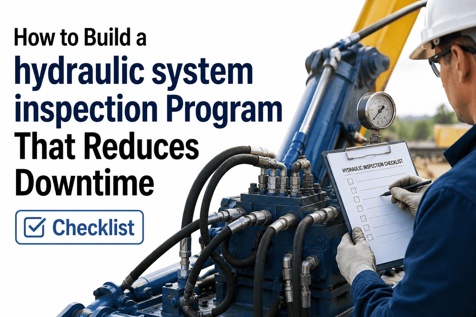
Hydraulic systems fail silently — pressure drops, seal wear, and contamination build over weeks before a catastrophic breakdown halts an entire fleet. A structured hydraulic system inspection program catches these signals early, converting expensive emergency repairs into planned maintenance actions. Fleet maintenance teams operating without a documented inspection program lose an average of 23 hours per hydraulic failure event to unplanned downtime. The gap between a functional hydraulic inspection program and a paper-based one is the gap between a work order raised before a seal fails and a crane or dump truck grounded on a job site. Sign Up Free to run guided hydraulic inspections across your fleet with Oxmaint, or Book a Demo to see how maintenance teams cut hydraulic downtime with inspection programs that actually get completed.
Build a Hydraulic Inspection Program That Runs Itself
Oxmaint gives maintenance teams guided hydraulic checklists, automatic work order generation on defect detection, and a real-time asset compliance dashboard — replacing paper logs with a program that scales across every machine in your fleet.
The 5-Phase Program Build Framework
Building a hydraulic inspection program that reduces downtime requires five sequential phases. Teams that skip phase 2 (asset criticality ranking) end up inspecting low-risk components as frequently as high-failure-rate assemblies — wasting inspection time and missing the failures that actually ground equipment.
List every hydraulic-dependent asset in the fleet: excavators, cranes, dump trucks, forklifts, and allied plant. For each asset, document the hydraulic circuit type, pump specification, reservoir capacity, and operating pressure range. This inventory becomes the master asset register that Oxmaint uses to assign inspection templates and route defect notifications to the correct technician.
Rank each asset by failure consequence: production impact, safety exposure, and replacement lead time. High-criticality assets receive daily pre-shift hydraulic checks. Medium-criticality assets receive weekly inspections. Low-criticality equipment receives monthly checks. Oxmaint enforces inspection frequency per asset — overdue inspections trigger supervisor escalation automatically.
Design inspection checklists around the four hydraulic component groups: fluid and contamination, pump and motor assembly, cylinder and actuator condition, and hose and fitting integrity. Each checklist item must require a measurable observation — fluid colour code, pressure gauge reading, or visible leak classification — rather than a pass/fail guess.
Define three defect tiers before the program launches: Out of Service (immediate removal from operation), Defect (monitor and schedule repair within 48 hours), and Advisory (log and trend for next planned service). Oxmaint converts any flagged inspection item into a work order automatically, with severity level, asset ID, and assigned technician pre-populated.
Track four KPIs: inspection completion rate per asset class, defect-to-work-order conversion time, mean time between hydraulic failures (MTBF), and repeat defect rate per component type. Repeat defects on the same component within 90 days indicate a systemic root cause that the inspection program is detecting but the repair program is not fixing.
Section 1: Hydraulic Fluid and Contamination Checklist
Fluid contamination accounts for over 70% of hydraulic system failures. These five checklist items are the first gate in every hydraulic inspection — no other component check is meaningful if the fluid condition is outside specification.
Fluid level — within min/max marks on sight glass or dipstick
Low fluid causes cavitation and pump damage within minutes of operation. Check reservoir level before every shift start on high-criticality assets. Any reading below the minimum operating mark is an immediate out-of-service condition. OOS — level below minimum mark
Fluid colour and clarity — amber/clear, no milky discolouration or dark contamination
Milky fluid indicates water ingress from a failed breather or heat exchanger. Dark fluid indicates oxidation or thermal degradation. Neither condition is safe for continued operation — fluid sampling and root cause identification required before restart. OOS — milky, foamy, or dark fluid
Reservoir breather cap — clean, seated correctly, no clogging visible
A blocked breather creates vacuum in the reservoir, accelerating cavitation at the pump inlet. Breather service is the lowest-cost contamination prevention action in any hydraulic system. Defect — clogged or unseated breather
Return line filter condition indicator — green zone, no bypass warning active
A filter operating in bypass is passing contaminated fluid through the entire hydraulic circuit. Replace immediately when indicator enters red zone — postponing filter service compounds contamination damage on every subsequent hour of operation. OOS — filter in bypass or red zone
Fluid temperature at rated load — within OEM operating range, no overheating
Sustained fluid temperature above 82°C (180°F) degrades seal elastomers and accelerates fluid oxidation. Log temperature readings at peak operating load to identify thermal management issues before they produce seal failures. Advisory — log temperature at every inspection
Section 2: Pump and Motor Assembly Checklist
Pump failure is the highest-cost single component event in a hydraulic system. These checklist items detect pump wear and drive problems before they produce complete circuit failure.
Pump noise at startup — no cavitation knock, whine, or intermittent pressure surges
Cavitation noise (rattling or knocking) indicates the pump is drawing air. Whining indicates wear or low fluid viscosity. Either symptom at startup is an immediate inspection trigger — operating a cavitating pump for even one hour accelerates internal damage exponentially. OOS — any cavitation or abnormal noise at startup
System pressure at rated load — within OEM specification, no fluctuation under load
Pressure fluctuations during operation indicate internal pump wear, a failing pressure relief valve, or a restriction in the circuit. Document pressure readings at each inspection — a trend of declining pressure over successive inspections predicts imminent pump failure. OOS — pressure below OEM specification at rated load
Pump case drain flow — within OEM specification, no excessive bypass at case drain port
Excessive case drain flow indicates internal pump wear — the pump is bypassing internally and losing volumetric efficiency. Measure against baseline at each scheduled service to detect wear curves before output pressure is affected. Defect — case drain flow above OEM specification
Drive coupling condition — no visible misalignment, no rubber insert deterioration
A deteriorated rubber coupling element transmits vibration to the pump inlet shaft, accelerating bearing wear. Visual inspection takes 30 seconds; replacing a pump bearing after shaft damage takes 4–6 hours and a parts lead time that grounds the equipment. Defect — any rubber insert cracking or deterioration
Pump mounting and fasteners — no excessive vibration, all mounting bolts secure
Loose pump mounting bolts cause misalignment that accelerates shaft seal wear and bearing failure. Check torque at every scheduled service interval. Vibration at idle that is not present at startup indicates a developing mounting or coupling issue. Defect — loose mounting or abnormal vibration at idle
Section 3: Cylinders and Actuator Checklist
Hydraulic cylinder failures combine performance risk with safety exposure. A leaking rod seal on mobile plant is both a fire hazard and a load-holding failure risk. These items must be completed before any lift or load operation.
Cylinder rod seals — no external leakage visible at any cylinder rod seal
A leaking rod seal drips hydraulic fluid onto hot exhaust components and creates a fire risk on mobile plant. Any external cylinder leakage is an immediate out-of-service condition. Rod scoring that caused the seal failure must be resolved before resealing — otherwise the new seal will fail within the same operating period. OOS — any external cylinder rod seal leakage
Rod surface condition — no scoring, pitting, or chrome layer damage visible
Rod scoring introduces abrasive particles behind the rod wiper on every stroke, destroying the new seal within a short operating period. A scored rod must be assessed for repair or replacement — resealing alone is not an adequate corrective action. OOS — any scoring or chrome damage on rod surface
Cylinder drift test — no load drift beyond OEM specification under rated load hold
Cylinder drift under load with no external leakage indicates internal bypass through worn piston seals. Test by holding the cylinder at full extension under rated load for 60 seconds — any movement beyond OEM specification requires seal inspection. Defect — drift beyond OEM specification under load hold
Rod wiper condition — no cracking, tearing, or debris ingestion visible behind wiper
A deteriorated rod wiper allows abrasive particles to enter the cylinder and score the rod surface. Wiper replacement is a 20-minute scheduled maintenance task; rod replacement after scoring is a 4-hour task with a 2–5 day parts lead time. Advisory — replace wiper at any sign of cracking or deterioration
Section 4: Hoses, Fittings, and Pipework Checklist
Hose failure at operating pressure is a safety event, not just a breakdown. These checklist items identify hose deterioration and fitting seepage before they produce a failure event on a live machine.
High-pressure hoses — no blistering, abrasion, kinking, or external damage on any hose
A blistering hydraulic hose is failing structurally and will rupture without further warning. Hose failure at 250+ bar operating pressure is a safety event. Inspect the full hose length — chafing against structure causes failure at the contact point, not at the fitting where leaks are usually first noticed. OOS — any blistering, kinking, or external damage
Hose routing and contact points — no contact with heat sources, sharp edges, or moving parts
Hose contact with exhaust manifolds or engine casings causes thermal degradation of the outer cover and inner liner. Log any hose contact with heat sources as an advisory — rerouting or heat shielding costs under an hour; internal liner damage can introduce contamination that destroys a hydraulic pump. Advisory — reroute or shield any hose contacting heat source
Fittings and port connections — no seepage at any fitting, torque marks aligned where present
A seeping fitting that is ignored at inspection becomes a failed fitting during operation. Document seepage location and fitting type — repeat seepage at the same fitting after re-torquing indicates a damaged seat or incorrect fitting specification for the operating pressure. Defect — any seepage at fittings or port connections
Hose clamps and supports — all clamps present, secure, and free from corrosion
Missing or corroded clamps allow hoses to move under pressure cycling, causing fatigue cracking at fitting ends. Check all clamps during the hose visual inspection — a missing clamp is a 2-minute fix; a hose end failure from fatigue cracking is a machine-down event. Defect — missing, loose, or corroded hose clamps
Hydraulic Inspection KPIs to Track
An inspection program without KPIs is a documentation exercise. These four metrics distinguish a program that reduces downtime from one that merely creates inspection records.
Frequently Asked Questions
Common questions from maintenance managers building hydraulic inspection programs for the first time or replacing paper-based processes.
Start Reducing Hydraulic Downtime With a Digital Inspection Program
Oxmaint replaces paper hydraulic inspection logs with guided mobile checklists, automatic work order generation, and a compliance audit trail — giving maintenance managers real-time visibility across every hydraulic asset in the fleet.