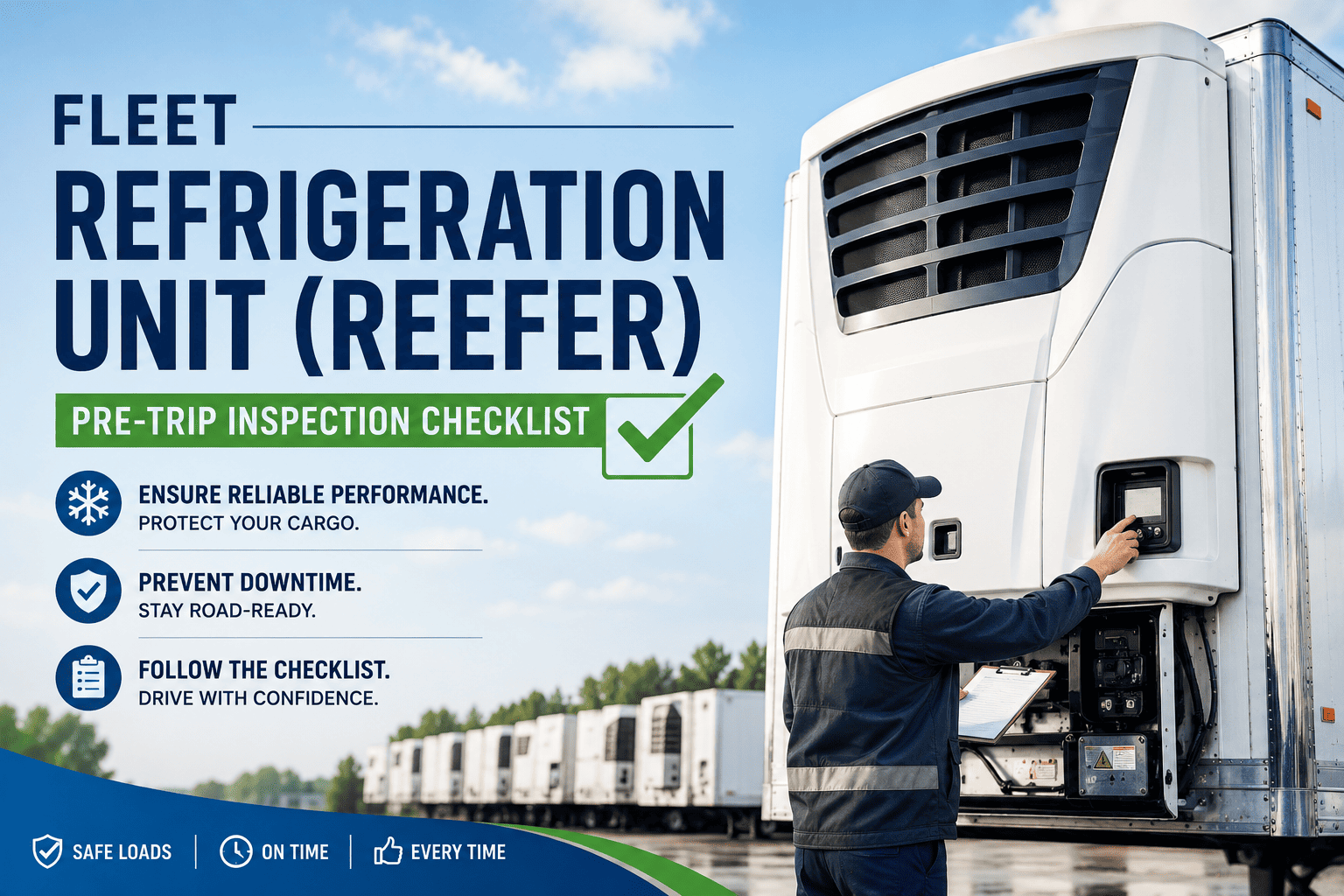
A reefer unit that drifts 4°F above setpoint during a 14-hour overnight haul does not just fail a temperature log — it potentially destroys the entire load, triggers a food safety investigation, and voids the carrier's cargo insurance coverage for that shipment. Refrigerated transport operates on tighter tolerances than any other fleet asset class: the refrigeration unit, door seals, floor drains, and temperature monitoring system must all function correctly simultaneously, and a failure in any single component can compromise the cold chain from origin to delivery. Oxmaint's reefer maintenance module schedules every PM task, captures temperature calibration results, and generates cold chain compliance records that satisfy both FMCSA and food safety audit requirements.
Reefer Performance Impact — Key Fault Metrics
Every reefer fault has a measurable impact on cargo temperature, fuel consumption, and compressor life. The metric cards below show how each major fault category affects performance — so technicians understand what is at stake when a PM task is deferred or a defect is left unresolved.
How Technology Is Advancing Reefer Fleet Maintenance
Temperature excursions used to be discovered at delivery — when the damage was already done and the cargo was already lost. Four technologies are shifting reefer maintenance from reactive incident management to predictive performance assurance, catching developing faults before they produce a temperature deviation that costs more than the unit's annual maintenance budget. Oxmaint connects all four into a single reefer fleet management platform.
1. Compressor and Engine System Checklist
The reefer compressor is the highest-wear, highest-cost component in the refrigeration system. Compressor failures account for over 40% of all reefer unit breakdown events — and most are preceded by weeks of measurable symptoms that a structured PM programme catches before the compressor seizes. Schedule reefer compressor PM with automated hour-based triggers on Oxmaint.
Compressor amp draw — measure at operating conditions
Measure compressor amp draw at steady-state operating conditions and compare to the manufacturer specification for current ambient temperature and setpoint. An amp draw 10% above specification indicates increased internal friction from worn bearings or reed valves. An amp draw 20% above specification at normal operating conditions requires immediate investigation — the compressor is approaching failure. Defect — 10%+ above spec
Compressor oil level and condition
Check oil level in sight glass — low oil indicates either consumption or a leak requiring investigation. Drain and inspect oil at the manufacturer's recommended interval — oil that appears dark, contains metal particles, or smells burnt indicates internal wear. Never operate a compressor with oil below the minimum sight glass level — compressor seizure typically follows within 2–4 operating hours. OOS — below minimum level
Refrigerant charge — suction and discharge pressure check
Connect manifold gauges and record suction and discharge pressures at steady state. Compare to manufacturer pressure-temperature chart for current conditions. Low suction pressure indicates a refrigerant undercharge or restriction. High discharge pressure indicates a condenser problem or overcharge. Any charge adjustment must be performed by a certified technician with Section 608 certification. Defect — outside PT chart range
Drive belts — tension, wear, and alignment
Inspect all belts for cracking, glazing, fraying, and correct tension. A belt deflection exceeding 1/2" under moderate finger pressure indicates a loose belt that will slip under compressor load. Misaligned belts wear 3× faster than correctly aligned belts and generate vibration that damages compressor shaft seals, causing refrigerant leaks within 500 operating hours. Defect — cracked or glazed
Reefer engine — fuel system, coolant, and oil service
Service the reefer engine at the hour-based interval specified by the manufacturer (typically 250–500 hours depending on unit model). Check fuel filter condition — a partially blocked fuel filter causes the engine to run lean, increasing operating temperature and accelerating valve seat wear. Verify engine coolant freeze protection at winter PM — reefer engines run at lower load than truck engines and lose coolant protection faster. Defect — overdue service
AI Digital Twin tip: Oxmaint's reefer digital twin tracks compressor operating hours, amp draw trend over successive PM events, and fuel consumption per unit of cooling — predicting compressor efficiency decline and scheduling a pre-emptive rebuild 300–400 hours before the unit would fail on route. See Oxmaint's predictive reefer PM scheduling.
2. Condenser and Evaporator Checklist
A condenser coil that is 30% blocked with road debris increases compressor discharge pressure by up to 25% — cutting cooling capacity, increasing fuel consumption, and shortening compressor life simultaneously. Evaporator ice build-up from a failed defrost cycle reduces airflow progressively until the unit cannot maintain setpoint regardless of compressor output. Both failures are completely preventable with regular cleaning and inspection.
Condenser coil — cleaning and fin condition inspection
Clean condenser fins with coil cleaner and low-pressure water at every PM event. Inspect fin condition — bent fins reduce airflow and should be straightened with a fin comb. A condenser with more than 20% of its fin area blocked will cause the discharge pressure to exceed the normal operating range, triggering high-pressure cutout and leaving the load unprotected until the unit manually resets. Defect — 20%+ blocked
Condenser fan motor and blade — operation and clearance
Check fan motor current draw — a motor drawing above its nameplate amperage is overheating and approaching failure. Verify blade clearance at all positions — a blade that contacts the shroud creates vibration that cracks motor mounts within 200 hours. Check fan direction — a reversed fan motor moves air the wrong way through the condenser coil, reducing cooling capacity by 40–60%. Defect — contact with shroud
Evaporator coil — ice build-up and airflow check
Inspect evaporator coil for ice accumulation between defrost cycles. Light frost on the coil surface is normal; ice that blocks more than 25% of the coil face indicates a defrost system problem requiring investigation. Measure evaporator airflow — a 20% reduction in airflow produces a 15°F temperature gradient across the trailer length that shows up as high temp readings at the front door end during loading. Defect — 25%+ ice coverage
Evaporator fan motors — current draw and blade inspection
Test each evaporator fan motor individually — a single failed motor reduces airflow by 33% on a 3-motor unit, creating a temperature gradient across the load that may not trigger the controller alarm but will cause partial cargo damage in temperature-sensitive loads like fresh produce. Check blade hubs for cracks — a failed blade hub causes sudden motor failure and an immediate trip off on high temperature. Defect — one motor failed
Defrost heater elements — resistance test all positions
Test each defrost heater element with an ohmmeter — a failed element reads open circuit and will not be visible during visual inspection. On a 3-element evaporator, one failed heater extends defrost cycle time by 35–50%, causing the evaporator to complete defrost with residual ice that accumulates haul-to-haul until airflow is significantly restricted. Defect — open circuit element
3. Temperature Controller and Monitoring System Checklist
The reefer controller is the brain of the refrigeration system — and a controller that displays the correct setpoint while producing incorrect actual temperatures is more dangerous than an obvious failure, because drivers and dispatchers trust the displayed reading. Controller calibration verification and temperature probe accuracy testing must be performed at every PM, not just when a temperature excursion is reported. Log controller calibration results and temperature probe readings digitally with Oxmaint.
Temperature controller calibration — verify against reference thermometer
Allow the unit to stabilise at setpoint, then compare the controller's displayed actual temperature to a calibrated reference thermometer placed at the evaporator return air position. Any deviation greater than ±1°F requires controller sensor calibration or probe replacement. A controller reading 3°F warmer than actual load temperature allows the load to be maintained at a higher temperature than the driver or dispatcher believes. OOS — deviation >2°F
Return air and discharge air probes — accuracy verification
Test return air probe and discharge air probe separately against a calibrated reference. Record both readings and the reference thermometer reading in the maintenance record — this creates the calibration documentation required for FSMA food safety audits. A probe that passes calibration check at PM should have its calibration date and result stored in the reefer's asset record. Defect — probe accuracy failure
High temperature alarm — test activation and notification
Test the high temperature alarm at 3°F above setpoint — the alarm must activate audibly and trigger a notification to the telematics system within the controller's specified response time. A high temperature alarm that sounds in the cab but does not transmit to dispatch is only useful if the driver checks the unit frequently — which most drivers cannot do safely during an interstate haul. Defect — no remote notification
Data logger — download, verify, and storage compliance
Download the data logger record at every PM and verify the temperature trace matches the controller's display history for the same period — any discrepancy indicates a sensor or logging fault. Verify data logger record retention covers the minimum period required for your commodity — FSMA-regulated foods require temperature records retained for 2 years minimum, retrievable within 24 hours of an inspection request. OOS — records not retrievable
Controller fault codes — retrieve and action all stored codes
Connect diagnostic tool and retrieve all stored fault codes — including passive codes that cleared themselves. A code that self-cleared may indicate a sensor fault that only activates under certain load or ambient conditions. Document all codes retrieved, their date stamps from the controller memory, and the action taken. Codes retrieved and not actioned are evidence of known defects in any food safety incident investigation. Defect — unactioned codes
PLC / SAP Integration tip: Reefer controller PLC fault codes that write directly to Oxmaint work orders eliminate the manual step between fault detection and technician assignment — when a probe failure code is logged at 2am at a truck stop, the maintenance manager has a work order in Oxmaint and parts reserved in SAP before the driver calls in the next morning. Book a demo to see PLC-to-work-order automation for reefer fleets.
4. Door Seals, Floor Drains and Structural Integrity Checklist
A reefer unit that performs perfectly cannot maintain setpoint inside a trailer with compromised door seals. A 1/4" gap in a rear door seal on a hot summer day introduces enough warm, humid air to raise return air temperature by 5–8°F during loading — forcing the unit to run continuously to compensate, increasing fuel consumption, and creating condensation inside the trailer that damages packaging and triggers mould growth in produce loads.
Rear door seals — gap inspection and compression test
Inspect all four sides of both rear door seals for cuts, compression set, and separation from the mounting channel. Close doors fully and pass a strip of paper around the entire perimeter — any position where the paper pulls out without resistance indicates a seal gap. A seal that allows a 1/4" gap around the lower corners on a 38°F frozen load allows enough moisture ingress to ice the door sill and jam the door closed at the delivery point. Defect — paper test fails
Nose mount and front wall seal — unit-to-trailer interface
Inspect the seal between the reefer unit and the trailer front wall opening. Any gap at the nose mount allows warm outside air to enter the trailer through the unit housing — bypassing the return air sensor and creating a warm spot in the nose area that is invisible to the controller but causes cargo damage in loads stacked against the front wall. Defect — visible gap
Floor drains — clearance and drain valve function
Verify all floor drain plugs can be removed and replaced easily. On refrigerated trailers that carry wet loads, a blocked floor drain allows meltwater to accumulate and freeze into a floor layer that increases the thermal mass the unit must overcome and creates a slip hazard at delivery. Check drain valve seals — a leaking drain valve allows outside air ingress at the floor level during winter operations. Defect — blocked drain
Floor, walls, and ceiling insulation — thermal integrity
Inspect floor boards and wall panels for moisture damage or delamination — wet insulation loses up to 70% of its R-value, requiring the reefer unit to run significantly harder to maintain the same setpoint. Check ceiling panels for moisture staining from roof seal failures. An infrared camera scan of the interior during a pre-load inspection reveals insulation hot spots invisible to the naked eye. Defect — moisture staining
Air chute and bulkhead — airflow distribution integrity
Inspect the air chute (ceiling duct) for tears, collapsed sections, or disconnection from the evaporator outlet. A damaged air chute concentrates cold airflow to one section of the trailer — creating a temperature gradient from front to rear that passes temperature checks at the probe position but allows cargo at the door end to warm 6–8°F above setpoint during a long haul. Defect — torn/collapsed section
We were losing two to three loads per quarter to reefer-related temperature excursions before we moved to Oxmaint. After implementing hour-based PM scheduling with digital calibration records, our temperature excursion rate dropped by 84% in the first year. The condenser cleaning programme alone — which we'd been doing inconsistently — saved us from three compressor failures that would have happened during summer peak season.
Reefer Fleet Maintenance — Key Performance Metrics
Fleets implementing structured hour-based reefer PM with digital calibration records reduce temperature excursion incidents by up to 84% compared to mileage-only service programmes.
40% of all reefer unit breakdown events involve the compressor — making compressor amp draw monitoring and oil analysis the single highest-ROI reefer PM investment available.
Average cargo loss value per reefer failure event on a full 53-foot trailer — the benchmark against which every reefer PM investment decision should be measured.
250-hour PM interval for high-utilisation reefer units (18+ hrs/day) provides the optimal balance between service cost and fault detection — catching developing issues before they reach failure threshold.
Frequently Asked Questions
Common questions from reefer technicians, fleet managers, and cold chain compliance officers about reefer unit maintenance, temperature monitoring, and FSMA documentation.
Every 250 hours for high-utilisation units running 18+ hours per day; every 500 hours for units averaging 8–12 hours daily. Use operating hours, not mileage — a reefer engine accumulates hours while stationary at a loading dock. Most Thermo King and Carrier Transicold units have hour meters that feed directly into telematics for automated PM scheduling.
The FDA Food Safety Modernization Act (FSMA Sanitary Transportation Rule) requires shippers and carriers to document temperature control procedures and maintain records for 12 months. Temperature monitoring device calibration records must be retained for 12 months after use. Records must be retrievable and provided to FDA within 24 hours of a written request during an inspection.
The four most common causes are: blocked condenser coil reducing heat rejection capacity, low refrigerant charge reducing compressor output, failed or ice-covered evaporator coil reducing airflow, and compromised door or nose-mount seals allowing warm air infiltration. Check condenser blockage first — it is the most frequent cause and the fastest to diagnose and correct on route.
Compare the controller's displayed actual temperature to a NIST-traceable reference thermometer at the return air probe position with the unit at steady state. Any deviation over ±1°F warrants calibration. Probes that are physically damaged, have corroded connectors, or have been replaced but not re-calibrated should be tested immediately — a post-replacement calibration check is not optional for FSMA compliance.
Section 608 of the Clean Air Act requires technicians who handle refrigerants to be certified by an EPA-approved certifying organisation. Only certified technicians may add or recover refrigerant from reefer systems. Carriers who allow uncertified technicians to perform refrigerant work face EPA civil penalties up to $44,539 per day per violation — and the violation attaches to the carrier, not just the technician.
Oxmaint tracks reefer unit operating hours from telematics integration, triggers PM work orders at the correct hour interval per unit, records probe calibration results with date and technician signature, stores data logger download records against the asset profile, and generates FSMA-ready temperature monitoring compliance documentation — all retrievable within 30 seconds of any audit request.