A juice bottling facility in California discovered that 12,000 bottles shipped over a three-day period contained fill volumes ranging from 15% under to 8% over the labeled amount. The root cause traced to a level sensor that had drifted out of calibration, reporting containers as full when they were not. Quality control sampling had not caught the problem because affected bottles were randomly distributed through production runs. The recall cost exceeded $280,000, but the damage to retailer relationships proved more lasting. Customer audits for the following two years scrutinized the facility's sensor verification procedures. Plants implementing structured filling line checklist protocols for sensor verification catch drift before it creates quality escapes, protecting both product integrity and customer confidence.
Sensors on filling lines make hundreds of decisions per minute: is a container present, is it positioned correctly, has it been filled to the target level, is a cap in place, is the label applied properly. When sensors misread, the consequences cascade. Fill level sensors that read high produce underfilled containers. Presence sensors that miss containers cause filling valves to cycle without product. Cap detection sensors that false trigger reject good product while missing actual defects. Each misread creates waste, reduces efficiency, or allows defective product to continue down the line.
Sign up to implement sensor verification checklists or book a demo to see how digital calibration tracking prevents sensor-related quality issues.
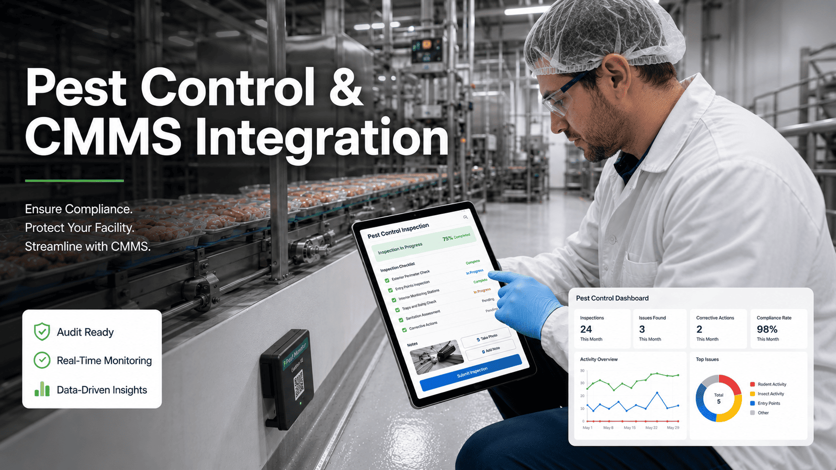
Sensor Verification
Filling Line Sensor Misread Prevention Checklist
Systematic verification procedures to ensure sensors read accurately, preventing quality escapes and production losses from misreads.
Of Fill Level Issues Trace to Sensor Problems
Detection Rate with Daily Verification Checks
Of Sensors Drift Beyond Tolerance Within 90 Days
$47K
average
Cost of Quality Escape from Undetected Sensor Drift
Understanding Filling Line Sensor Failures
Filling lines rely on multiple sensor types working together: photoelectric sensors detect container presence and position, ultrasonic or capacitive sensors measure fill levels, proximity sensors verify cap placement, vision systems inspect labels and codes. Each sensor type has characteristic failure modes that systematic verification can detect before they cause production problems.
Sensor misreads rarely announce themselves dramatically. Instead, performance degrades gradually as sensors drift, become contaminated, or develop intermittent faults. A fill level sensor might read 2% high today, 3% high next week, and 5% high the week after. By the time the deviation becomes obvious, thousands of containers may have been affected. Structured verification catches this drift early, when calibration adjustment resolves the issue rather than product recall.
67%
of fill level quality issues trace directly to sensor problems rather than filling equipment malfunctions. The filling system performs correctly, but sensors report incorrect information that causes the control system to make wrong decisions. Verifying sensor accuracy addresses the majority of fill-related quality problems.
Effective sensor verification requires understanding what each sensor measures, how it can fail, and what verification methods detect those failures. A photoelectric presence sensor requires different verification than an ultrasonic level sensor. The checklists in this guide address each sensor type with appropriate verification procedures matched to their failure modes.
Sign up for Oxmaint to track sensor calibration status and verification history across your filling lines.
Daily Sensor Verification Checklist
Complete this verification at the start of each production shift. These quick checks confirm sensors are responding correctly before production begins, catching problems that developed overnight or during changeover.
Container Presence Sensors
Clean sensor faces (emitter and receiver)
Remove product residue, dust, and moisture from all photoelectric sensors
Verify indicator lights respond to container passage
Pass test container through each sensor location, confirm light changes state
Check sensor mounting and alignment
No loose brackets, sensors aimed at target area
Verify cable connections secure
Connectors fully seated, no damaged cables
Fill Level Sensors
Clean level sensor faces
Remove product buildup from ultrasonic transducers or capacitive probes
Run verification container through filler
Fill 3 test containers, weigh each: ___g, ___g, ___g | Target: ___g +/- ___g
Compare sensor reading to actual fill weight
Deviation within tolerance: Yes / No | If No, initiate calibration
Check HMI level display responds smoothly
No erratic readings, jumps, or freezes during fill cycle
Cap/Closure Sensors
Clean cap detection sensor
Remove residue from sensor face and reflector
Test with known good container
Properly capped container passes without reject
Test with known defective container
Missing/crooked cap triggers reject: Pass / Fail
Reject System Verification
Verify reject confirmation sensor
Sensor confirms container entered reject bin
Test reject mechanism operation
Trigger test reject, confirm container diverted
Digital Verification Records with Calibration Tracking
Oxmaint maintains complete sensor verification history with automated calibration due date alerts and trend analysis for drift detection.
Common Sensor Types and Failure Modes
Understanding how each sensor type fails enables targeted verification that catches problems before they affect production. Different sensor technologies have distinct failure patterns requiring specific verification approaches.
Common Applications
Container presence detection
Position verification at stations
Label presence confirmation
Cap/closure detection
Failure Modes
Lens contamination reducing sensitivity
Alignment drift from vibration
LED degradation over time
Cable damage causing intermittent signals
Verification Method
Clean lenses daily, verify response to known good/bad targets, check indicator light function
Common Applications
Non-contact fill level measurement
Tank level monitoring
Container height verification
Failure Modes
Transducer contamination affecting signal
Temperature drift in uncompensated sensors
Foam interference with liquid surfaces
False echoes from nearby objects
Verification Method
Compare reading to known reference height, verify at multiple fill levels, check temperature compensation
Common Applications
Fill level detection through container walls
Product presence in sealed containers
Material detection regardless of color
Failure Modes
Sensitivity drift requiring recalibration
Product buildup on sensing surface
Humidity effects on sensing threshold
Electrical noise interference
Verification Method
Test with empty container (no detect) and full container (detect), verify switching point consistency
Common Applications
Label position and quality inspection
Date/lot code verification
Fill level visual inspection
Cap orientation and seal inspection
Failure Modes
Lens contamination degrading image quality
Lighting changes affecting detection
Inspection parameters drifting
Focus shift from vibration
Verification Method
Run known good and known bad samples, verify reject triggers correctly, check image quality on HMI
Weekly Calibration Verification Checklist
Weekly verification uses reference standards to confirm sensors remain within calibration tolerance. This more detailed check catches drift that daily verification might miss.
Fill Level Calibration Check
Fill calibration container to known weight
Use certified scale, target weight: ___g, actual: ___g
Compare sensor reading to reference
Sensor reading: ___ | Reference: ___ | Deviation: ___%
Test at low fill point (underfill detection)
Fill to reject threshold, confirm reject triggers: Pass / Fail
Test at high fill point (overfill detection)
Fill to upper threshold, confirm reject triggers: Pass / Fail
Document deviation from previous week
Last week: ___% | This week: ___% | Trend: Stable / Drifting
Presence Sensor Sensitivity Check
Check signal strength indicator (if available)
Signal strength: ___% | Minimum acceptable: 70%
Test detection at edge of sensing range
Container at far edge of range still detected: Yes / No
Verify no false triggers without container
Run 30 seconds without containers, count false triggers: ___
Inspection Sensor Performance
Run test set of known defects (10 samples)
Defects caught: ___ / 10 | Target: 10/10
Run test set of known good product (10 samples)
False rejects: ___ / 10 | Target: 0/10
Review reject rate from previous week
Total rejects: ___ | Confirmed defects: ___ | False positive rate: ___%
Calibration Status Review
Check calibration due dates for all sensors
Sensors due within 30 days: _______________________
Verify no sensors past calibration due date
All current: Yes / No | If No, escalate immediately
Sensor Troubleshooting Procedures
When verification reveals a sensor problem, systematic troubleshooting identifies the root cause and appropriate corrective action. Follow these procedures before calling for calibration service.
01
Erratic or Unstable Readings
Check cable connections for looseness or damage. Verify power supply voltage at sensor. Look for electrical noise sources nearby (VFDs, welders). Clean sensor face thoroughly. If intermittent, observe while flexing cables to find break.
02
Consistent Offset (High or Low)
Indicates calibration drift. Clean sensor face first as contamination can cause offset. Check mounting position has not shifted. Verify correct product recipe selected. If offset persists after cleaning and position check, recalibration required.
03
No Response to Target
Check indicator light status with no target present. Verify power supply present. Check if sensor in teach/setup mode. Test with alternate known-good target. Swap sensor with spare to isolate sensor vs. wiring problem.
04
False Triggers (Sees Target When None Present)
Check for reflective surfaces in sensing path. Verify alignment not shifted to detect nearby objects. Look for product splash or mist entering sensing area. Reduce sensitivity if adjustable. Shield from ambient light if photoelectric.
05
Missed Detections (Fails to See Target)
Clean sensor face and target surface. Check target is within sensing range. Verify target material compatible with sensor type. Increase sensitivity if adjustable. Check for obstructions in sensing path. Verify proper alignment.
06
Temperature-Related Issues
Note if problem correlates with line warm-up. Check sensor specification for operating temperature range. Verify sensor not exposed to radiant heat from nearby equipment. Some drift during warm-up is normal; excessive drift indicates compensation failure.
Track Sensor Performance and Predict Calibration Needs
Oxmaint trend analysis identifies sensors drifting toward failure, enabling proactive calibration before production impact.
Sensor Misread Response Procedure
When sensor misreads are discovered, immediate response limits the scope of the affected product. Follow this procedure to contain the issue and prevent recurrence.
Stop the line if misread affects food safety or regulatory compliance
Quarantine product produced since last known good verification
Identify time range of potential exposure
Notify quality assurance of potential issue
Document discovery time, sensor ID, and observed deviation
Review sensor verification records for drift pattern
Check when problem likely began based on trend data
Identify root cause (contamination, calibration, damage, etc.)
Evaluate product in quarantine against specification
Determine disposition of affected product
Recalibrate or replace affected sensor
Verify correct operation with test samples
Run verification at increased frequency initially
Update calibration interval if drift indicates need
Document corrective actions and verification of effectiveness
Frequently Asked Questions: Filling Line Sensor Verification
How often should fill level sensors be calibrated?
Most fill level sensors should be formally calibrated quarterly, with weekly verification checks between calibrations. However, calibration frequency should be based on your sensor's stability history. Sensors showing drift at weekly verification need more frequent calibration. Document your rationale for calibration intervals based on verification data.
What's the acceptable tolerance for fill level sensors?
Tolerance depends on your product specification and regulatory requirements. Most food products allow +/- 1-2% of target fill. Your sensor tolerance should be tighter than your product specification to ensure the specification is always met. If your product allows +/- 2%, your sensor should be calibrated to +/- 1% or better.
How do we verify vision system inspection sensors?
Vision systems require verification with known defect samples. Maintain a test set of samples representing each defect type the system should detect, plus known good samples.
Sign up for Oxmaint to track vision system verification results and identify degrading detection performance before quality escapes occur.
Should operators be allowed to adjust sensor sensitivity?
Operators should not adjust calibrated sensors. Sensitivity adjustments made to compensate for problems often mask underlying issues and can create quality escapes. If a sensor requires frequent adjustment, that indicates a problem requiring maintenance attention. Document any adjustments with before/after readings and justification.
What records do we need for sensor calibration compliance?
Calibration records should include sensor identification and location, calibration date and next due date, as-found and as-left readings, reference standard used with traceability documentation, tolerance applied, pass/fail determination, and calibration technician identification. Retain records for minimum 2 years or per your quality system requirements.
Prevent Sensor-Related Quality Issues
Oxmaint sensor verification checklists, calibration tracking, and trend analysis catch drift before it affects product quality, protecting your brand and customer relationships.