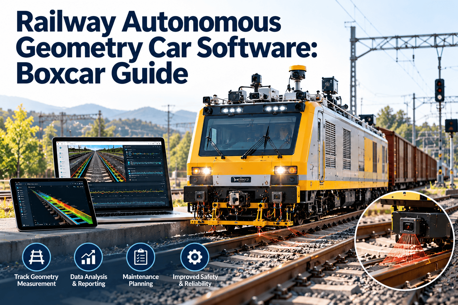
An autonomous geometry car is a measurement instrument that happens to ride on wheels. Its value depends on two things staying healthy at once: the vehicle underneath and the sensors on board. If either slips, the track data it collects stops being trustworthy. This guide explains how to manage a small autonomous geometry fleet, such as two boxcars and one passenger service unit, and how railway CMMS software like Oxmaint keeps calibration, mechanical upkeep, and data quality in one record.
Railway Autonomous Geometry Car Software: Boxcar Guide
Track geometry data is only as reliable as the car that collects it. Manage boxcar and passenger-service autonomous units as instruments and rail vehicles at the same time.
What an Autonomous Geometry Fleet Really Is
Autonomous track geometry measurement systems are mounted on vehicles that run in regular service, so measurement happens without a dedicated inspection train. The Federal Railroad Administration has long used automated inspection to support compliance with the Track Safety Standards in 49 CFR Part 213.
The vehicle side
- Wheelsets, bearings, and trucks
- Brakes and couplers
- Car body and structure
- Interchange or host railroad requirements
The instrument side
- Lasers, cameras, and inertial sensors
- Positioning and speed inputs
- Onboard computers and storage
- Power, communications, and data upload
Most fleet systems manage only one side well. A mechanical program ignores calibration, or a measurement program ignores wheel and bearing condition. Both failures corrupt the data.
The Measurement Chain You Are Protecting
Geometry measurements include gage, alignment, crosslevel, profile, and warp. Each depends on a chain of components working together.
Break any link and a track defect may be missed, or a false defect may send a crew to a location that is fine.
Maintenance Tasks by Subsystem
The table shows a practical way to organize recurring work. Intervals come from the equipment manufacturer, the operating railroad, and your own engineering judgment.
| Subsystem | Typical recurring work | What to record |
|---|---|---|
| Wheels and trucks | Wheel profile and wear checks, bearing inspection, truck component review | Measurements, defects, replacement dates |
| Brake system | Brake tests, component inspection, air system leak checks | Test results, parts, inspector |
| Measurement sensors | Cleaning, alignment checks, calibration verification | Calibration date, procedure, pass or fail |
| Positioning equipment | Antenna checks, speed sensor verification, data reference checks | Test results, offsets, corrections |
| Power and electronics | Battery or generator service, wiring and connector inspection | Voltage readings, replacements |
| Data and communications | Storage health, software updates, upload tests | Version numbers, failed uploads, fixes |
Keep Every Geometry Unit Ready to Measure
Track calibration, mechanical condition, and data delivery against each car, so your fleet produces measurements the engineering team can trust.
The Calibration Problem
Calibration is the heart of a measurement fleet and the easiest thing to lose track of. A sensor that is slightly off will still produce confident-looking numbers.
- Define the calibration interval and trigger events for each sensor, such as after a repair or sensor replacement.
- Store the procedure, reference standard, and acceptance criteria on the work order.
- Record as-found and as-left values so drift is visible over time.
- Block the unit from being marked ready for service when calibration is overdue.
- Note which data files were collected between the last good calibration and the failure.
That last step matters for data users. If a sensor drifted, the track team needs to know which runs to treat with caution.
Boxcar Units and Passenger Units Behave Differently
Treating all geometry cars the same is a common planning mistake. Their duty cycles, hosts, and access windows differ.
| Factor | Boxcar in freight service | Passenger service unit |
|---|---|---|
| Route pattern | Follows train assignments, which can be irregular | Follows timetables and repeated routes |
| Access for maintenance | Depends on yard or shop availability along the route | Depends on terminal layover and overnight windows |
| Wear drivers | Heavy axle loads on adjacent cars, in-train forces, yard handling | Higher speeds, frequent stops, vibration exposure |
| Data coverage | Wide geographic spread, uneven repeat frequency | Frequent repeats on a defined corridor |
| Host requirements | Freight interchange and host railroad rules | Passenger equipment and operator requirements |
Software should let each unit carry its own plan, hosts, and inspection intervals while still rolling up to fleet-level reporting.
From Car Health to Track Decisions
The reason to keep the fleet healthy is what its data produces. Geometry exceptions feed track maintenance, and the loop only works when each step is recorded.
Operational Impact of Losing a Unit
With only a few autonomous units, each one carries a large share of the program. Downtime is not an inconvenience; it is a coverage gap.
What Oxmaint Handles for a Geometry Fleet
Oxmaint is a maintenance management platform. It does not process geometry data, but it holds the equipment record that makes the data defensible.
Without a unit-level record
- Calibration certificates in email folders
- Shop work tracked on paper or by phone call
- No view of what was replaced since the last run
- Readiness decided by whoever remembers
With Oxmaint
- Asset records for each car, subsystem, and sensor
- Preventive schedules for calibration and inspections
- Work orders with parts, labor, and sign-off
- Dashboards showing overdue tasks and unit readiness
Records a Regulator or Host Railroad May Ask For
Requirements depend on the owner, operator, and host railroad. Keeping a complete record means you can answer without scrambling.
- Inspection and test records for brakes, wheels, and structural components
- Calibration and verification history for each measurement system
- Repair history with parts, labor, and approvals
- Run logs showing dates, routes, and unit status
- Software and firmware versions installed at each point in time
- Documentation of data gaps and the reasons for them
Condition-Based Maintenance for Measurement Equipment
Fleets with onboard diagnostics can move beyond fixed intervals. Self-check results, sensor signal quality, and bearing temperature data can signal that a unit needs attention before it fails.
- Capture self-check results and error codes after every run.
- Define the thresholds that trigger an inspection work order.
- Track repeat faults by component to identify weak parts.
- Compare calibration drift across units to catch environmental or mounting issues.
- Adjust preventive intervals based on what the history shows.
Planning Maintenance Around Run Schedules
The best maintenance window is one that does not cost data coverage. Plan shop visits when a unit's route is least critical, and line up parts and labor before it arrives.
Common Failure Modes and What They Do to the Data
Linking failure modes to data effects helps teams prioritize repairs and decide which runs to trust.
| Failure mode | Effect on measurements | Maintenance response |
|---|---|---|
| Dirty or fogged optical sensor | Noisy or missing readings, false exceptions | Cleaning routine, enclosure inspection, seal replacement |
| Sensor misalignment after impact | Consistent offset in gage or alignment values | Alignment check and recalibration before the next run |
| Worn wheel profile | Altered contact conditions and ride behavior | Wheel measurement, truing, or wheelset replacement |
| Positioning or speed sensor fault | Defects reported at the wrong location | Sensor test, reference check, replacement |
| Power instability | Dropped data, unplanned shutdowns mid-run | Battery or generator service, connector inspection |
| Storage or upload failure | Lost or late data files | Storage health check, communications repair, file recovery |
Handoffs Between Mechanical, Electronics, and Track Teams
Three groups touch a geometry unit, and each sees a different part of the problem. The record has to carry information between them.
Mechanical team
- Reports wheel, truck, and brake findings
- Flags work that could affect sensor alignment
- Releases the car mechanically
Electronics team
- Verifies and calibrates sensors
- Updates software and records versions
- Releases the instrument for service
Track engineering
- Reports data quality concerns
- Requests repeat runs on key segments
- Consumes exceptions and assigns track work
Spares Strategy for a Very Small Fleet
With three units, there is no pool of identical cars to borrow from. Spare parts become the main protection against long downtime.
- Identify single points of failure, such as the positioning unit or main processor
- Stock critical spares with lead times that exceed your acceptable downtime
- Track reorder points and supplier lead times in the inventory record
- Record serial numbers when a spare replaces a failed part
- Keep calibration equipment and reference standards tracked as assets themselves
KPIs That Show Fleet Health
A short list of indicators helps a small team see problems early. Choose measures that connect equipment condition to data delivery.
The bar lengths above illustrate the display style only and are not real performance data. Your own targets should reflect your operating agreements.
Interchange and Host Railroad Considerations
A boxcar that operates in general service or on another railroad's lines may fall under interchange rules and the host railroad's own requirements. A passenger unit has its own equipment rules.
- Confirm which inspection and repair standards apply to each unit with its owner and operator
- Store applicable rules and intervals as notes on the asset record
- Record who performed each repair and under what authority
- Keep documentation ready for audits by hosts and oversight agencies
A Practical Rollout for a Three-Unit Fleet
A small fleet can be live quickly. Focus first on the items that most affect data trust.
Questions to Ask Before Choosing Software for Autonomous Units
Use these questions to test whether a system can handle instrument fleets, not just ordinary rolling stock.
- Can each sensor be tracked as its own asset with its own calibration schedule?
- Can calibration status stop a unit from being marked ready for a run?
- Can work orders capture as-found and as-left readings in structured fields?
- Can crews complete checklists on mobile devices in a yard or shop with weak signal?
- Can reports separate mechanical downtime from instrument downtime?
- Can the record show which software version was installed on a given run date?
If the answer to several of these is no, the system will push your team back into spreadsheets for the most important records.
Learning From Fleet History
A clean maintenance record becomes a diagnostic tool over time. With only a handful of units, patterns are easy to spot if the data is structured.
- Compare repeat sensor faults across units to separate part defects from mounting or environment issues
- Review which tasks most often run late and whether windows or staffing are the cause
- Track how often calibration is lost after mechanical repairs and add a verification step if needed
- Check which spares are used most and adjust reorder points
- Look at downtime by cause to decide where improvement pays off first
Over a few cycles, that history shows which components fail repeatedly and where preventive intervals should tighten or relax.
Frequently Asked Questions
Does the software analyze geometry data?
Why track calibration in a CMMS?
Can one system cover boxcar and passenger units?
How does this help with data quality?
Is it hard to set up for three units?
Give Your Autonomous Fleet a Single Source of Truth
Connect calibration, mechanical condition, and shop work for every geometry unit, and keep your track data on firm ground.