A 45 kW chilled water pump bearing does not fail without warning. It fails after progressing through four measurable degradation stages over weeks or months — and the intervention window that prevents a bearing replacement from becoming an emergency motor replacement, a flooded mechanical room, or a data centre thermal event is Stage III, when Ball Pass Frequency Outer Race (BPFO) harmonics are clearly present in the FFT spectrum but overall vibration is still below ISO 10816-3 Zone D. The HVAC technician who reads an overall vibration of 3.8 mm/s RMS, compares it to the 4.5 mm/s Zone B boundary, and plans the bearing for the next scheduled maintenance window is doing predictive maintenance correctly. The HVAC technician who checks the same pump monthly with a route-based handheld collector but never trends the readings — so the 1.2 mm/s from January, 1.9 mm/s from February, 2.8 mm/s from March, and 3.8 mm/s from April exist in four separate work orders with no trend line connecting them — is performing vibration data collection, not vibration analysis. The difference is the database, the trend model, and the AI that reads the slope before a human notices the numbers are going in one direction. Book a 30-minute demo to see how Oxmaint's Predictive Maintenance AI stores per-asset vibration baselines, tracks measurement trends, identifies FFT fault signatures, and generates work orders weeks before the bearing failure an uncorrelated spreadsheet row would have missed — or start a free trial and connect your first rotating asset today.
Predictive Maintenance AI · HVAC Rotating Assets · ISO 10816-3
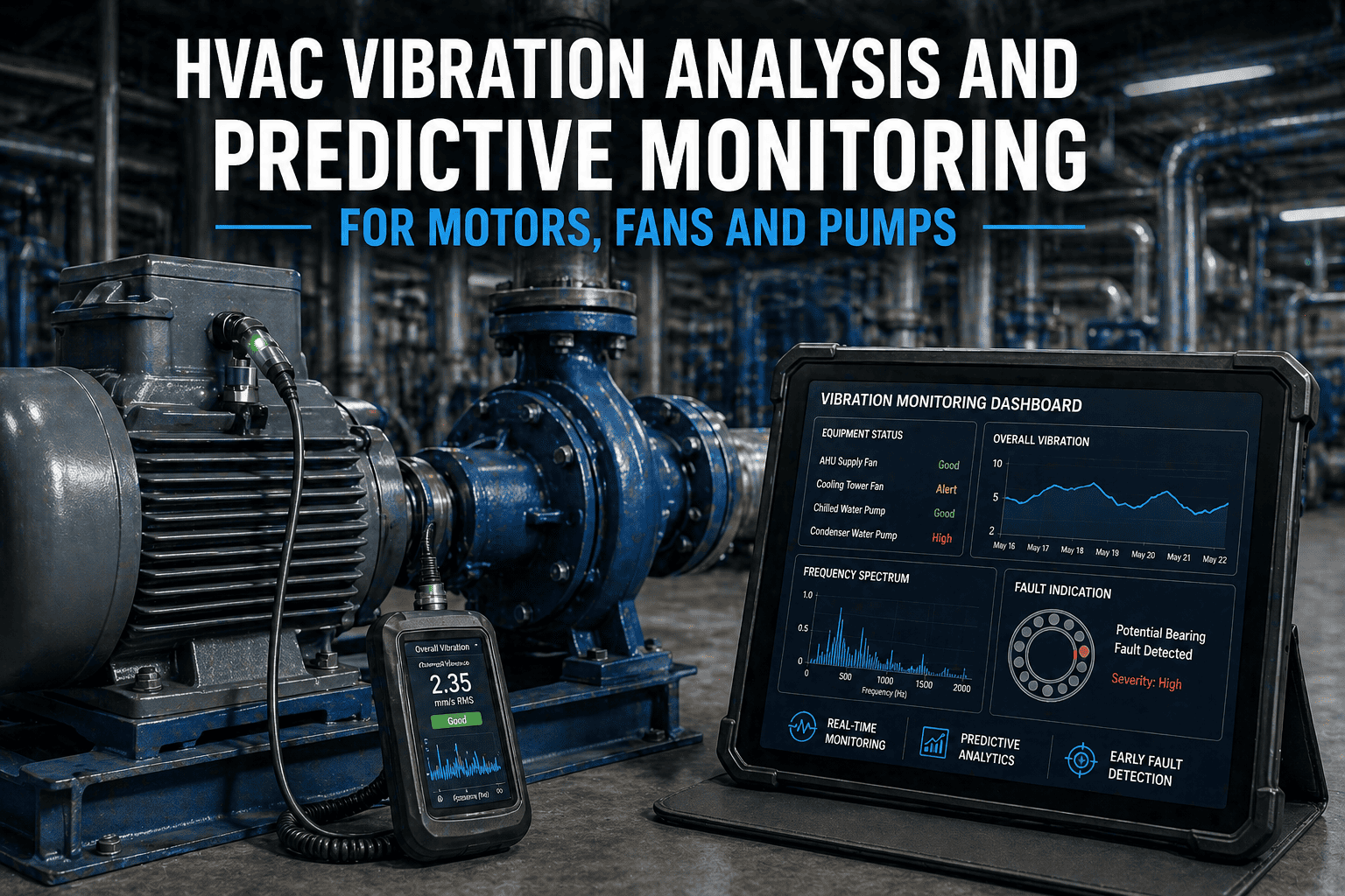
HVAC Vibration Analysis and Predictive Monitoring for Motors, Fans, and Pumps
ISO 10816-3 severity zones, FFT fault signature identification, asset-specific measurement routes, and the bearing degradation progression that defines the difference between calendar-based inspection and genuine predictive maintenance.
ISO 10816-3 — Vibration Severity Zones (Group 2: 15–75 kW)
Zone A
< 1.8 mm/s RMS
New / recently commissioned
Zone B
< 4.5 mm/s RMS
Acceptable — unrestricted long-term operation
Zone C
< 7.1 mm/s RMS
Investigate — not suitable for continuous operation
Zone D
> 7.1 mm/s RMS
Immediate shutdown — damage occurring
The Four Bearing Degradation Stages — Where to Intervene and When
Every rolling element bearing progresses through four measurable degradation stages before failure. The optimal predictive maintenance intervention is Stage III — when fault frequencies are clearly identifiable in the FFT spectrum but overall vibration is still in Zone B or early Zone C. Waiting for Zone D means waiting until the window for planned repair has closed.
I
Ultrasound / High-Frequency Emission
Very early-stage bearing defects produce high-frequency stress waves detectable by ultrasonic testing instruments (30–50 kHz range) — not yet visible in standard vibration FFT. Overall vibration within Zone A. No symptoms.
Action: No immediate action. Establish baseline if not yet set. Flag for increased monitoring frequency.
II
Defect Frequencies Emerging in FFT
Bearing defect frequencies (BPFO, BPFI, BSF, FTF) begin appearing in the vibration spectrum at low amplitudes. Overall vibration still in Zone A or low Zone B. No audible change. No temperature rise.
Action: Increase measurement frequency. Order replacement bearing. Plan maintenance window.
III
Clear Fault Frequency Signatures — Optimal Intervention Window
Intervene Here
BPFO, BPFI, or BSF clearly present with harmonics in FFT. Overall vibration in Zone B or early Zone C. Bearing replacement at this stage is a planned maintenance event — 2 to 6 months of advance warning typically available.
Action: Schedule bearing replacement during planned maintenance window. Replace bearing and realign before returning to service.
IV
Discrete Frequencies Disappear — Catastrophic Imminent
Discrete bearing defect frequencies replaced by broadband noise floor. Overall vibration in Zone C or D. Bearing clearance has increased to looseness condition. Catastrophic failure is imminent — machine should not continue operating.
Action: Immediate shutdown. Emergency bearing replacement. Inspect shaft, housing, and adjacent components for secondary damage.
FFT Fault Signature Matrix — What the Frequency Spectrum Tells You
Broadband overall vibration measurement tells you something is wrong. FFT spectrum analysis tells you what is wrong and which component is causing it. The matrix below maps the five primary HVAC rotating equipment fault types to their frequency domain signatures, enabling targeted corrective action rather than reactive replacement.
Fault Type
Frequency Signature
Dominant Direction
Common HVAC Cause
Corrective Action
1× RPM dominant
Stable phase, amplitude increases with speed²
Radial (horizontal + vertical)
Fan blade fouling, erosion, or ice accumulation; broken impeller vane; uneven deposit on pump impeller
Field balancing ($1,500–4,000); clean fan blades; restore impeller symmetry
2× RPM dominant
High axial component (>50% of radial); 180° phase shift across coupling
Axial + radial; 2× strong
Pump-motor coupling misalignment after maintenance; thermal growth misalignment on hot-service pumps; worn flexible coupling element
Laser alignment; coupling element replacement
Multiple harmonics 1×, 2×, 3×, 4×+
Erratic amplitudes; sub-harmonic peaks ½×, ⅓× possible
Radial; unstable pattern
Loose mounting bolts; worn bearing housing bore; soft foot condition; loose fan hub on shaft
Tighten mounting; check soft foot; replace worn housing; correct before balancing
Non-synchronous: BPFO, BPFI, BSF, FTF
BPFI has ±1× sidebands; BPFO no sidebands (outer race stationary); BSF 2× dominant
Radial and axial (depending on fault location)
Inadequate lubrication; contamination; overload; misalignment causing localised raceway wear; normal fatigue life reached
Stage III: plan replacement; Stage IV: immediate shutdown
Belt frequency and harmonics
Belt freq = 1× RPM × (sheave circumference / belt length); harmonics if belt worn or loaded
Radial; belt speed frequency
Worn belt; mismatched sheave sizes; incorrect belt tension; sheave eccentricity or misalignment in belt-drive CRAC and AHU fans
Replace belt; check tension; align sheaves; check sheave runout
Oxmaint Predictive Maintenance AI stores the per-asset vibration baseline, trends every measurement against it, and flags frequency signature patterns that indicate the specific fault type — so your HVAC team receives a diagnostic work order, not just an overall vibration alert.
HVAC Vibration Measurement Checklist — By Asset Type and Interval
Vibration data collection without trending is data waste. Every measurement below must be stored against the specific asset ID in the CMMS — not in a route file, not in a spreadsheet, not in a technician's email inbox. The trend model requires the same measurement point, the same measurement direction, and the same operating conditions to be comparable.
WEEKLY
Operator-level — overall vibration check on critical assets
PUMP
Record overall vibration at drive end and non-drive end bearing housings on all primary chilled water and condenser water pumps — measure in radial horizontal, radial vertical, and axial directions. Compare against ISO 10816-3 Zone B boundary (4.5 mm/s RMS for Group 2). Any reading in Zone C or above requires a work order before the next scheduled route
Record: Overall RMS velocity (mm/s) per measurement point per asset ID · Ref: ISO 10816-3 · Role: Predictive maintenance technician
FAN
Record overall vibration on AHU supply fans, return fans, and cooling tower fans — bearing housings at drive end and non-drive end, horizontal and vertical. Fan imbalance from blade fouling presents as elevated 1× RPM in FFT and rising overall vibration trending over weeks, not sudden spikes — weekly measurement captures the trend before Zone C is reached
Record: Overall RMS velocity per fan bearing position · Role: Predictive maintenance technician
MONTHLY
FFT spectrum collection — fault frequency identification
MOTOR
Collect FFT spectrum on all HVAC drive motors above 15 kW — store in CMMS per asset, per measurement point, with RPM confirmed at time of measurement. Identify presence of 1× (imbalance), 2× with high axial (misalignment), multiple harmonics (looseness), or non-synchronous bearing defect frequencies (BPFO, BPFI, BSF, FTF). Confirm bearing defect frequencies against bearing datasheet parameters for each motor model
Record: FFT spectrum data file + identified frequencies + ISO zone classification · Role: Category II vibration analyst or AI-assisted analysis via Oxmaint
PUMP
Collect FFT spectrum on pump bearings — check for pump cavitation signature (sub-synchronous broadband noise at 20–40% of 1× RPM) which indicates insufficient NPSH or throttled suction valve. Pump cavitation is often misdiagnosed as imbalance or bearing fault — the sub-synchronous location of cavitation noise in the FFT distinguishes it from all other fault types and demands a hydraulic solution, not a mechanical one
Record: FFT spectrum with sub-synchronous range visible · Role: Category II vibration analyst
FAN
Check for blade pass frequency (BPF = number of blades × RPM) elevation in centrifugal fan FFT — elevated BPF amplitude indicates uneven blade loading from fouling, damaged blades, or insufficient clearance. BPF elevation combined with 1× elevation confirms simultaneous imbalance and aerodynamic loading issue — both must be addressed before the fan can return to baseline vibration
Record: FFT spectrum with BPF calculated and logged per fan blade count · Role: Vibration technician
QUARTERLY
Alignment verification + bearing lubrication + belt drive inspection
MOTOR
Verify pump-motor shaft alignment using laser alignment tool — compare against OEM tolerance. Misalignment above tolerance shows as 2× dominant with high axial vibration, 180° phase shift across coupling in vibration data. Correct alignment before it becomes a bearing failure: 25–30% of premature bearing failures are caused by misalignment. Confirm coupling element condition at the same time
Record: Laser alignment report with as-found and as-left readings · Role: Alignment-certified technician
ALL
Re-grease bearings that are not sealed/grease-packed for life — use OEM-specified grease type and quantity. Over-greasing causes as much bearing damage as under-greasing: excessive grease churning generates heat that accelerates degradation. Log grease type, quantity, and bearing housing temperature before and after greasing. Bearing temperature rise of more than 10°C above ambient during steady operation is an early indicator of lubrication or load issue
Record: Bearing lubrication log with grease type, quantity, pre/post temperature · Role: HVAC technician
FAN
Inspect belt-drive fan systems — check belt tension against OEM specification using tension gauge (not by deflection feel). Measure belt wear and confirm belt set is matched (mixed-age belts in multi-belt drives cause uneven load distribution and premature belt failure). Inspect sheave grooves for wear and confirm sheave alignment with straight edge. Quarterly belt tensioning is the minimum interval — stretched belts cause slippage and additional 1× component in vibration
Record: Belt tension measurement (Newtons or pounds) vs OEM specification + sheave condition assessment · Role: HVAC technician
ANNUAL
Full condition assessment — balance, resonance check, baseline reset
FAN
Full fan balancing verification — coast-down vibration measurement before cleaning to establish fault baseline, then clean fan wheel completely, then re-measure and balance in-place if 1× RPM component is above Zone A threshold after cleaning. Fan blade fouling is the primary cause of AHU and cooling tower fan imbalance; cleaning alone rarely restores original balance — in-place balance correction is required for complete remediation
Record: Pre-clean, post-clean, and post-balance vibration readings per direction · Role: Field balancing technician
ALL
Reset per-asset vibration baselines — compare annual measured data against the commissioning baseline and update the CMMS baseline record if the machine has been overhauled, rebalanced, or realigned. A baseline that dates from original commissioning and was never updated after a bearing replacement or motor swap provides misleading trend context. The trend model is only as good as the baseline it compares against
Record: Baseline reset log with reason for update and new baseline values per measurement point · Role: Predictive maintenance engineer
HVAC Vibration Monitoring KPIs — Metrics That Prove the Programme Is Working
| KPI |
Measurement |
Target |
Programme Failure Signature |
| % assets with current baseline | Assets with baseline measurement on record / Total rotating assets | 100% | Below 80% = trend analysis unreliable for most assets |
| Stage III interventions vs Stage IV | Planned bearing replacements (Stage III) / Emergency replacements (Stage IV) | >80% planned | Below 50% planned = monitoring frequency or trend analysis failing |
| Mean time between bearing failures | Total operating hours / Number of bearing replacements per period | Increasing trend year-on-year | Flat or declining = lubrication or alignment practice not improving |
| Fault correctly typed before repair | Correct fault pre-diagnosis (imbalance/misalignment/bearing) vs repair finding | >85% match rate | Below 70% = analysts not using FFT fault signatures, only overall level |
| Route completion rate | Measurements completed on schedule / Measurements due | 100% | Missed routes = gaps in trend data that break predictive model continuity |
"The single biggest mistake in HVAC vibration monitoring programmes is confusing data collection with analysis. I routinely audit facilities that have been collecting quarterly vibration measurements on their HVAC rotating equipment for three or four years, with good route compliance, good technician training, and good instrumentation — and they still have emergency bearing failures. When I pull the historical data, every failed bearing shows a clear Stage III warning in the FFT from 6 to 10 weeks before the failure, with overall vibration trending from 2.1 to 3.4 mm/s over 5 measurement cycles. Nobody acted on it because nobody was looking at the trend — they were looking at whether the number crossed the alarm threshold that week. Predictive maintenance is not a threshold alarm system. It is a trend analysis system that compares each measurement against the asset's own history, identifies the rate of change, and triggers an action recommendation when the slope crosses a defined intervention threshold — not when the value crosses a fixed limit. That is the difference between calendar-based vibration inspection and genuine AI-assisted predictive maintenance."
Anita Sharma, P.Eng., CAT III Vibration Analyst
Professional Engineer (Mechanical) · Category III Vibration Analyst (ISO 18436-2) · 20 years HVAC and building services predictive maintenance programme design · Author: Rotating Equipment Reliability in Commercial HVAC, Applied Predictive Maintenance Series · Certified Reliability Leader (CRL)
Frequently Asked Questions
What are the ISO 10816-3 vibration severity zones and which applies to HVAC equipment?
ISO 10816-3 defines four zones for industrial rotating machines above 15 kW:
Zone A (<1.8 mm/s RMS for Group 2, 15–75 kW) — new or recently commissioned;
Zone B (<4.5 mm/s) — acceptable for unrestricted long-term operation;
Zone C (<7.1 mm/s) — investigate and plan corrective maintenance;
Zone D (>7.1 mm/s) — immediate shutdown, damage is occurring. Most HVAC equipment (pumps 15–75 kW, AHU fans, cooling tower fans, CRAC compressors) falls within Group 2. Above 75 kW applies Group 1 limits, which are slightly more permissive due to larger machine mass.
Book a demo to see how Oxmaint applies ISO 10816-3 zone boundaries per asset class automatically.
How do bearing defect frequencies (BPFO, BPFI, BSF, FTF) differ from imbalance and misalignment in FFT spectra?
The key distinction is that bearing defect frequencies are non-synchronous — they do not fall at integer multiples of shaft running speed (1×, 2×, 3×). BPFO, BPFI, BSF, and FTF are calculated from bearing geometry (ball diameter, pitch diameter, contact angle, ball count) and appear at characteristic non-integer frequencies in the FFT. BPFI has ±1× sidebands; BPFO has no sidebands; BSF often has 2× dominant. By contrast, imbalance appears at exactly 1× RPM; misalignment at 2× RPM with high axial; looseness at multiple integer harmonics. Any peak at a non-synchronous frequency that matches a calculated bearing defect frequency is strong evidence of a developing bearing fault.
How far in advance can vibration analysis predict a bearing failure?
Bearing defect frequencies typically become clearly identifiable in the FFT spectrum
2 to 6 months before catastrophic failure — this is Stage III, the optimal intervention window. The exact lead time depends on operating speed, load, lubrication condition, and contamination levels. Faster machines (above 1,500 RPM) in contaminated environments have shorter warning windows than slower, clean machines. The warning window is compressed when measurements are taken infrequently — monthly measurement with AI trend analysis provides more reliable advance warning than quarterly manual threshold checks.
Start a free trial to configure monthly vibration trending on your HVAC rotating assets.
What causes vibration in HVAC fans and pumps that is not a bearing fault?
The four non-bearing vibration causes most common in HVAC equipment are: imbalance (fan blade fouling, erosion, or ice accumulation — 35–40% of all HVAC vibration problems; presents as elevated 1× RPM); misalignment (pump-motor coupling after maintenance — 25–30% of premature bearing failures; presents as elevated 2× with high axial); looseness (loose mounting bolts or worn bearing housing bore — presents as multiple harmonics with erratic amplitudes); and pump cavitation (insufficient NPSH or throttled suction — presents as sub-synchronous broadband noise at 20–40% of 1× RPM, not a mechanical fault and requires hydraulic correction).
How does Oxmaint Predictive Maintenance AI support HVAC vibration analysis?
Oxmaint stores per-asset vibration baselines and every subsequent measurement against the asset's own history. The AI compares each new measurement against the baseline trend, calculates the rate of change, and generates a work order when the slope indicates Stage II or Stage III degradation — not when a fixed threshold is crossed. The AI identifies the fault type from FFT signature patterns (imbalance, misalignment, bearing fault) and includes a diagnostic recommendation in the work order, so the assigned technician arrives knowing what to look for and what parts to bring, not just that a vibration alert was triggered. All measurements are stored against asset IDs with timestamp, RPM at measurement, and analyst attribution — building the trend database that makes every subsequent prediction more accurate.
The Bearing Failure Your Spreadsheet Missed Was in the Trend. Oxmaint AI Reads the Trend.
Oxmaint Predictive Maintenance AI stores per-asset vibration baselines, identifies FFT fault frequency signatures (BPFO, BPFI, imbalance, misalignment), calculates degradation rate from consecutive measurements, and generates diagnostic work orders at Stage II or III — weeks or months before the Stage IV emergency that calendar-based inspection was too infrequent to prevent.