Approximately 30% of VAV boxes in typical commercial buildings are operating with faults at any given time — and the majority of those faults are invisible to the building automation system because they fall below alarm thresholds while still wasting 5 to 30% of HVAC energy. A VAV box whose airflow sensor has drifted 12% below calibration is not in alarm. A VAV box whose damper is stuck at 65% open when the zone is unoccupied and calling for minimum airflow is not in alarm. A VAV box running a minimum airflow setpoint that was set during initial commissioning for a high-density office layout that is now a storage room is not in alarm. None of these faults are detectable from the BAS trending screen without intentional analysis — which is why ASHRAE Guideline 36 now mandates automated fault detection and diagnostics (AFDD) as part of high-performance VAV sequences, and why California Title 24 Part 6 Section 140.4.r now requires Guideline 36 programming for non-residential HVAC systems with DDC to the zone level as of the 2025 Energy Code. The gap between a VAV system that was commissioned correctly and one that is performing correctly five years later is almost entirely a maintenance and monitoring gap. Book a 30-minute demo to see how Oxmaint's Preventive Maintenance platform schedules VAV box inspection routes, tracks damper position trends, flags drifted airflow sensors, and documents the actuator and reheat coil condition data that transforms a building's VAV fleet from a fault-generating liability into an optimised zone control asset — or start a free trial today.
Preventive Maintenance · Airflow & Zone Control · ASHRAE Guideline 36
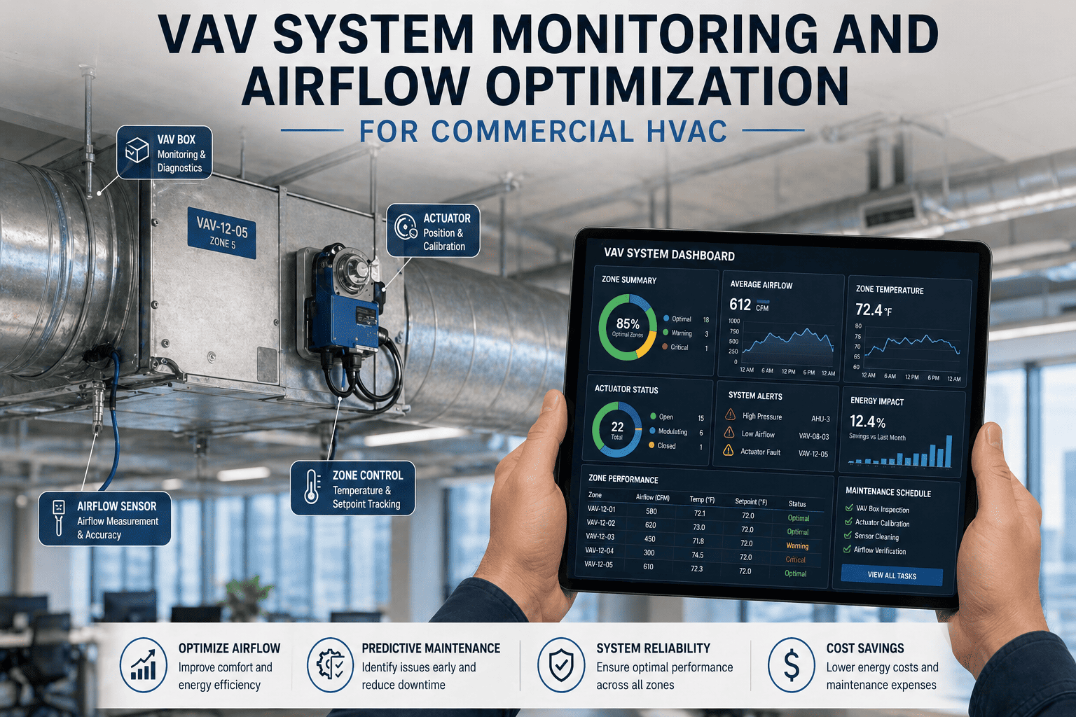
VAV System Monitoring and Airflow Optimisation for Commercial HVAC
The three fault types that account for most VAV energy waste, the ASHRAE Guideline 36 sequences that prevent them, the maintenance disciplines that catch them before they accumulate, and the zone performance analytics that prove the system is performing at design intent.
30%
Of VAV boxes in commercial buildings operating with faults — DOE Building Technologies Office
5–30%
HVAC energy wasted by undetected VAV faults in commercial buildings
50%
Fan power reduction at partial load with optimised ASHRAE Guideline 36 VAV sequences
10–30%
Energy reduction when minimum airflow setpoints corrected to actual ventilation needs (ASHRAE RP-1515)
The Three VAV Fault Types That Account for Most Energy Waste — And Why They Stay Hidden
Every VAV fault that wastes energy falls into one of three categories. What makes them dangerous is not their severity — most individual faults are small. What makes them dangerous is that a building with 200 VAV boxes can have 60 of them in some fault state simultaneously, none severe enough to trigger a BAS alarm, all of them degrading system performance continuously.
Fault 01 — Drifted Airflow Sensor
MechanismPitot-tube or averaging cross airflow sensors accumulate dust on sensing elements over time, causing progressive under-reading. A sensor reporting 85% of actual flow causes the controller to open the damper wider to reach setpoint — over-supplying the zone while the BAS reports normal operation
Why hiddenNo alarm is configured for sensor drift in most BAS implementations. The zone temperature may still be satisfied — the sensor error manifests as excess airflow, not comfort complaint
Energy impact10–15% excess airflow on affected boxes = fan and conditioning energy wasted in proportion to drift magnitude
DetectionAnnual pitot traverse vs BAS reported flow; quarterly DP sensor zero-check; cross-reference flow against damper position trend
Fault 02 — Stuck or Hunting Damper
MechanismActuator mechanical failure, linkage wear, or debris accumulation on damper blade causes the damper to remain at fixed position (stuck) or oscillate continuously between positions (hunting). Stuck-open during unoccupied periods is the highest-energy fault; stuck-closed causes comfort complaints and over-pressurises the duct branch
Why hiddenStuck dampers only generate alarms when the zone temperature drifts significantly from setpoint — moderate stuck positions can persist for months without triggering any alarm if the zone is partially served
Energy impactA 200-box building with 10% stuck-open during unoccupied hours wastes approximately the same energy as running the AHU at 10% higher flow all night
DetectionBAS trend log review: damper position not tracking control signal; flow not responding to setpoint changes; position constant despite varying zone loads
Fault 03 — Incorrect Minimum Airflow Setpoints
MechanismMinimum airflow setpoints are set at commissioning to serve the zone's design occupancy and ventilation load. When occupancy changes, space uses change, or the design was conservative, the minimum continues to supply more air than the actual ventilation requirement — wasting fan and conditioning energy at all occupied hours
Why hiddenThis is a configuration fault, not a mechanical fault. BAS shows normal operation. No alarm. No trend deviation. Only visible through deliberate comparison of the current minimum setpoint against the actual ASHRAE 62.1 ventilation requirement for current occupancy
Energy impactASHRAE RP-1515: correcting minimum airflow setpoints to actual ventilation requirements achieves median 10–30% energy reduction across the VAV fleet
DetectionAnnual minimum flow audit: compare each box's current minimum setpoint against ASHRAE 62.1 calculation for actual current zone occupancy and space use type
ASHRAE Guideline 36 — The Control Sequences That Prevent VAV Faults from Accumulating
ASHRAE Guideline 36 High-Performance Sequences of Operation formalises the VAV control logic that prevents faults from persisting undetected. California Title 24 Part 6 (2025 edition) now mandates Guideline 36 programming for non-residential systems with DDC to the zone level. Understanding which sequences require active maintenance to function correctly is essential for any FM team managing a Guideline 36 system.
Supply Air Temperature Reset
AHU supply air temperature is raised when all zones can be served at higher temperature — reducing cooling energy and reheat simultaneously. Requires all zone temperature sensors to be accurately calibrated; a single zone with a drifted sensor calling for maximum cooling blocks the entire building's reset
Annual zone temperature sensor calibration verification against reference instrument — every zone, not just complaint zones
Duct Static Pressure Trim and Respond
Duct static pressure setpoint is reduced until at least one VAV box is nearly fully open — minimising fan energy while maintaining adequate pressure for all zones. Requires accurate damper position feedback; a stuck-open box at full travel prevents the setpoint from trimming down correctly
Quarterly damper position verification — confirm BAS reported position matches physical damper position via manual override test or BAS command-response check
Demand-Controlled Ventilation (DCV)
Minimum airflow is reduced for zones below design occupancy based on CO₂ or occupancy sensor feedback. CO₂ sensor drift directly causes over-ventilation (high CO₂ reading → unneeded fresh air increase) or under-ventilation (low CO₂ reading → ASHRAE 62.1 minimum not met)
Annual CO₂ sensor calibration against certified reference gas; CO₂ cross-reference check between BAS reading and portable analyser at each sensor location
Automated Fault Detection and Diagnostics (AFDD)
Guideline 36 AFDD continuously compares each VAV box's actual airflow, damper position, and zone temperature against expected values — generating fault notifications for stuck dampers, sensor drift, and control sequence deviations. Fault suppression logic prevents AHU source faults from generating cascading false VAV terminal alarms
Monthly AFDD fault log review — all faults must be triaged, assigned to a work order, and resolved or accepted with documented reasoning within the same calendar month
Oxmaint schedules VAV box inspection routes, tracks trend log reviews as documented PM tasks, and stores actuator calibration, airflow sensor zero-check, and reheat coil inspection records per box — creating the maintenance history that proves Guideline 36 AFDD is being actioned, not ignored.
VAV System Maintenance Disciplines — Six Practices That Keep the Fleet Performing at Design Intent
01
Airflow Sensors
Annual pitot traverse calibration — the only method that finds drift
VAV airflow sensors measure the differential pressure across a pitot tube or flow averaging cross. Dust accumulation on sensing elements causes under-reading that worsens gradually over time. Annual commissioning-grade pitot traverse measurements at each VAV box, compared against the BAS-reported flow, identifies sensors that have drifted beyond the ±10% commissioning tolerance. Quarterly differential pressure zero-check (with duct at zero flow) identifies sensing element blockage or transducer offset without requiring full traverses.
IntervalAnnual pitot traverse · Quarterly DP zero-check
02
Damper Actuators
Quarterly stroke confirmation — the ASHRAE Guideline 36 prerequisite
Actuator stroke confirmation verifies that the damper physically travels from minimum to maximum position in response to the BAS control signal — and that the reported damper position in the BAS matches the physical position within 5%. A quarterly actuator stroke test is the minimum interval for commercial VAV systems: command each box to minimum airflow setpoint and confirm physical damper position corresponds; command to maximum and confirm. Any discrepancy between commanded, reported, and physical position indicates actuator mechanical failure, linkage wear, or control signal wiring fault.
IntervalQuarterly actuator stroke test per zone · ASHRAE Guideline 36 Section 5
03
Zone Temperature Sensors
Annual calibration — the hidden blocker of supply air temperature reset
Zone temperature sensors are the input to the VAV control loop and to the ASHRAE Guideline 36 supply air temperature reset sequence. A zone sensor reading 1.5°C high will call for maximum cooling continuously, preventing the entire building's supply air temperature from resetting upward — costing energy on every other zone in the system. Annual calibration of every zone temperature sensor against a reference thermometer in the same air space identifies sensors that have drifted beyond the ±0.5°C accuracy required for Guideline 36 reset sequences to function correctly.
IntervalAnnual calibration against reference instrument · ±0.5°C tolerance
04
Minimum Setpoint Audit
Annual flow minimum review against current ASHRAE 62.1 occupancy
Minimum airflow setpoints should be set to the ventilation requirement of the zone under current occupancy and space use — not the design occupancy from the original commissioning year. An annual minimum flow audit compares each box's current minimum setpoint against the ASHRAE 62.1-2019 ventilation calculation for its actual current occupancy and space type. ASHRAE RP-1515 found median energy reductions of 10–30% when minimums were corrected across a commercial building fleet — this is the highest-ROI single action available in VAV system optimisation.
IntervalAnnual — or immediately after any space use or occupancy change
05
Reheat Coils
Annual resistance test and quarterly valve/coil inspection
VAV boxes with electric reheat coils require annual resistance testing to confirm coil element continuity and that resistance is within OEM specification — degraded resistance indicates element breakdown that reduces heating capacity and increases energy consumption per unit of heat delivered. Hot water reheat coil VAV boxes require quarterly valve stroke verification (similar to damper actuator stroke test) and annual flow rate confirmation. A valve stuck open on a hot water reheat box will overheat the zone and simultaneously increase system loop temperature drop.
IntervalAnnual resistance test (electric) or flow check (hot water) · Quarterly valve inspection
06
Trend Log Analysis
Monthly BAS trend review — the systematic fault detection that manual inspection misses
Manual physical inspection of VAV boxes finds mechanical and visual defects. BAS trend log analysis finds the control-layer faults — sensors drifting over months, dampers hunting within the normal operating range, zones continuously demanding heating and cooling simultaneously (simultaneous heating and cooling fault), and boxes with zero response to setpoint changes. A monthly trend review of every zone's 30-day temperature, flow, and damper position data, compared against expected control response, is the systematic complement to quarterly physical inspection — and the only method to reliably detect the configuration faults that are invisible to visual inspection.
IntervalMonthly trend log review — all zones, all BAS points · Document findings in CMMS
VAV Zone Performance KPIs — Metrics That Prove the System Is Performing at Design Intent
| KPI |
Measurement |
Target |
Fault Signature |
| Airflow sensor accuracy | BAS-reported flow vs pitot traverse measurement | Within ±10% of traverse | Beyond ±10% = sensor replacement or cleaning required; re-zero DP transducer |
| Damper position accuracy | BAS reported position vs physical damper position at commanded setpoint | Within ±5% stroke | Beyond ±5% = actuator linkage wear, actuator motor fault, or feedback potentiometer failure |
| Zone temperature sensor accuracy | BAS reading vs calibrated reference thermometer in same air space | Within ±0.5°C | Beyond ±0.5°C = reset sequences compromised; sensor replacement required |
| Simultaneous heating and cooling rate | % of occupied hours where zone heating active while supply air below zone setpoint | < 2% of occupied hours | Above 5% = control sequence fault, deadband too narrow, or reheat valve not closing fully |
| Hunting damper rate | Zones with damper position change frequency above 2 cycles/minute during steady-state operation | 0 hunting zones | Hunting = controller gain too high, sensor noise, or mechanical backlash in actuator linkage |
| Minimum flow setpoint compliance | Actual minimum flow during unoccupied vs ASHRAE 62.1 minimum for current occupancy | Within ±5% of ASHRAE 62.1 minimum | More than 15% above ASHRAE 62.1 minimum = over-ventilation — energy waste without ventilation benefit |
"The 30% fault prevalence figure from the DOE is not describing catastrophic failures — it is describing the accumulation of small, sub-alarm-threshold degradation events across a fleet of VAV boxes that nobody is systematically monitoring. A building with 300 VAV boxes and quarterly physical inspection is inspecting each box four times per year. A building with 300 VAV boxes and monthly BAS trend log review is reviewing each box twelve times per year — and finding the control-layer faults that the physical inspection never reaches. The energy savings from correcting minimum airflow setpoints alone, which cannot be found by physical inspection, consistently represent 10 to 30% of HVAC energy consumption. That number is sitting in the BAS trend data of almost every commercial building that has not done a deliberate minimum flow audit since the original commissioning. ASHRAE Guideline 36 AFDD is beginning to automate some of this detection — but the AFDD output is only useful if there is a CMMS receiving the fault notifications, assigning them to named technicians, tracking resolution, and building the documented history that proves the system is being maintained at design intent. Without that loop, the faults are detected and forgotten."
James Okonkwo, PE, BEMP, HBDP
Licensed Professional Engineer · Building Energy Modelling Professional (ASHRAE) · High Performance Building Design Professional (ASHRAE) · 18 years commercial HVAC commissioning and VAV system optimisation · ASHRAE Guideline 36 implementation specialist · California Title 24 compliance consultant
Frequently Asked Questions
What are the most common VAV box faults and why do they go undetected?
The three most common VAV fault types are
drifted airflow sensors (pitot sensing elements accumulate dust, causing under-reading that makes the damper open wider than needed),
stuck or hunting dampers (actuator mechanical failure or linkage wear causes fixed or oscillating position), and
incorrect minimum airflow setpoints (design-era minimums not updated to reflect actual current occupancy and space use). All three go undetected because they fall below BAS alarm thresholds: the zone may still satisfy temperature setpoint, just inefficiently. The DOE Building Technologies Office estimates 30% of VAV boxes in commercial buildings operate with at least one of these faults continuously.
Book a demo to see how Oxmaint schedules the monthly trend log review that finds control-layer faults.
What does ASHRAE Guideline 36 require for VAV system maintenance?
ASHRAE Guideline 36 defines high-performance sequences for VAV systems including supply air temperature reset, duct static pressure trim-and-respond, demand-controlled ventilation, and automated fault detection and diagnostics (AFDD). The AFDD sequences generate fault notifications for stuck dampers, sensor drift, and control sequence deviations. California Title 24 Part 6 (2025 edition) now mandates Guideline 36 programming for all non-residential HVAC systems with DDC to the zone level. For the sequences to function correctly, zone temperature sensors must be within ±0.5°C calibration accuracy annually, and damper position feedback must be verified quarterly. Without these maintenance disciplines, the Guideline 36 sequences optimise against inaccurate inputs and produce degraded results.
How much energy can be saved by correcting VAV minimum airflow setpoints?
ASHRAE RP-1515 found
median energy reductions of 10–30% across commercial buildings when minimum airflow setpoints were corrected to actual ventilation requirements per ASHRAE 62.1-2019. This is the highest-ROI single maintenance action available for most VAV systems — because minimum setpoints are set at commissioning for design occupancy and are rarely revisited when space use or occupancy changes. Fan power alone drops 50% at partial load when VAV sequences are fully optimised (ASHRAE). The minimum flow audit requires no equipment replacement — only deliberate comparison of each zone's current setpoint against its ASHRAE 62.1 calculation for current actual occupancy.
Start a free trial to track minimum flow setpoints per zone in Oxmaint.
How often should VAV box damper actuators be inspected and calibrated?
Quarterly actuator stroke confirmation is the minimum interval for commercial VAV systems. The stroke test commands each box to its minimum and maximum airflow setpoints via the BMS and verifies that the measured airflow (within ±10% per commissioning standard) and physical damper position correspond to the BAS-reported position. Annual deep inspection adds linkage condition check, actuator torque verification, and control wiring insulation resistance test. Actuators that report position correctly to the BAS but do not achieve the commanded physical position (a control-layer discrepancy) are identified by the stroke test but not by any alarm — making quarterly stroke testing the only reliable detection method.
How does Oxmaint support VAV system preventive maintenance?
Oxmaint registers each VAV box as an individual asset with its zone ID, design minimum and maximum airflow, reheat type, and maintenance history. Quarterly actuator stroke tests, annual airflow sensor calibration, annual zone temperature sensor calibration, and annual minimum setpoint audits are scheduled as separate PM work orders per box — ensuring no zone is missed in a large building fleet. Monthly trend log review is a documented PM task with required completion confirmation, ensuring ASHRAE Guideline 36 AFDD fault notifications are actioned within the same month rather than accumulating. Every calibration result is stored against the asset record, building the documented history that demonstrates Guideline 36 compliance for Title 24 and customer audits.
30% of Your VAV Boxes Are Wasting Energy Right Now. Monthly Trend Analysis Finds Them.
Oxmaint Preventive Maintenance schedules quarterly actuator stroke tests, annual airflow sensor calibration, zone temperature sensor verification, and minimum setpoint audits per VAV box — and tracks ASHRAE Guideline 36 AFDD fault log reviews as documented monthly PM tasks, ensuring every control-layer fault is assigned, resolved, and documented before it becomes a year of accumulated energy waste.