VAV Box and Zone Control Inspection Checklist for Smart HVAC Systems
By james smith on April 28, 2026
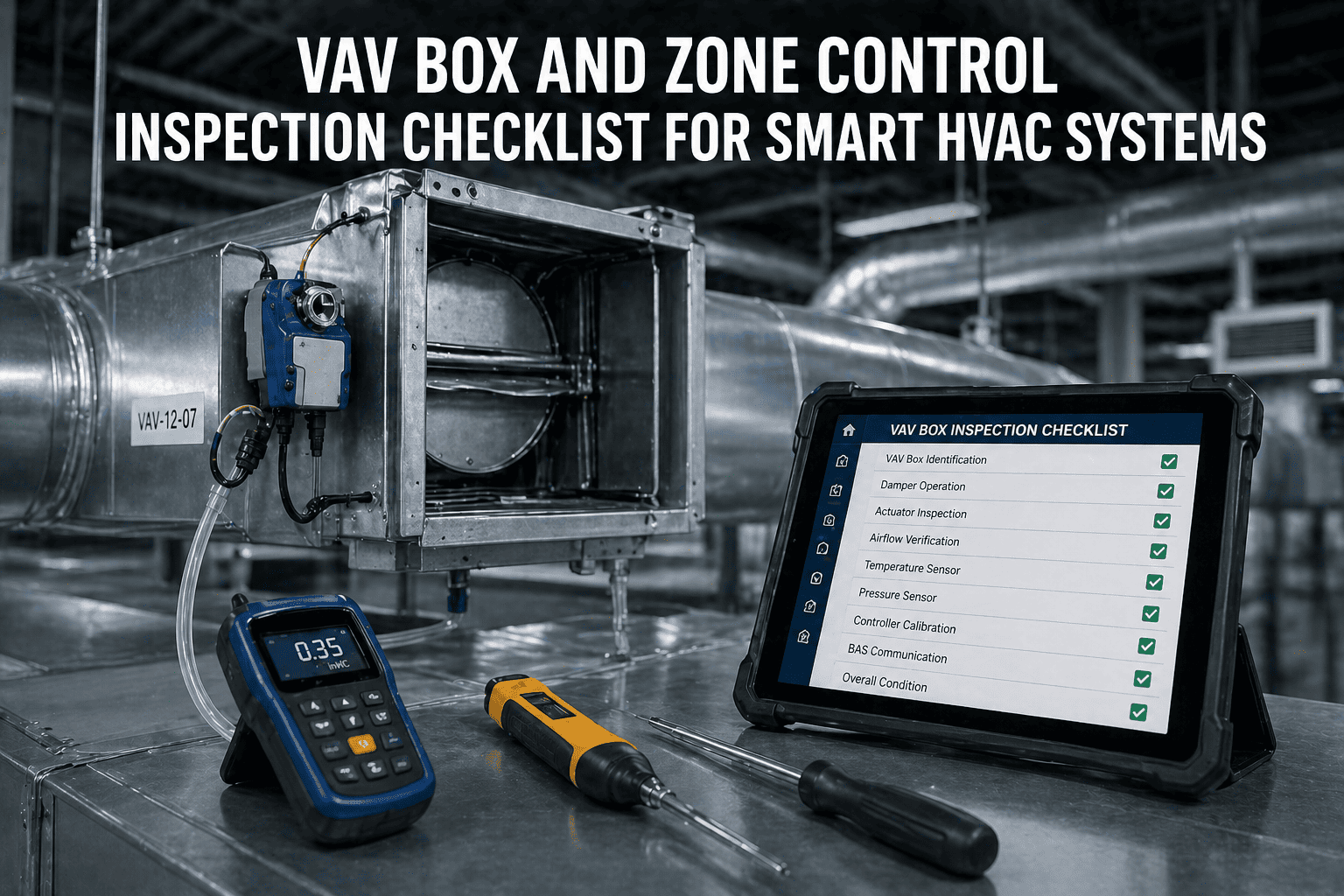
A VAV box inspection that produces a completed paper form is not a VAV box inspection — it is a signature on paper. A VAV box inspection that ends with a pass/fail result per component, a measured airflow reading in the CMMS compared against the design value, a documented damper stroke test result, and a photo of the controller status screen is an inspection that prevents the 30% fault prevalence rate the DOE Building Technologies Office attributes to under-maintained commercial VAV fleets. The distinction matters because VAV box faults — stuck dampers, drifted airflow sensors, mis-seated actuators, BAS communication dropouts — are not visible to the occupant until the zone is either always cold or always hot, and they are not visible to the BAS until they have been wasting energy long enough to produce a comfort complaint. The inspection checklist below provides pass/fail criteria for every component in a VAV box or zone control terminal unit, including the airflow measurement tolerance (±10% of design per commissioning standard), the actuator stroke acceptance criterion (physical position within 5% of BAS-reported position), and the controller communication verification steps that confirm the BAS is receiving accurate data from the box it thinks it is controlling. Book a 30-minute demo to see how Oxmaint's Preventive Maintenance platform digitises this checklist per VAV box ID — with technician sign-off, measured values, and photo evidence stored against each asset — or start a free trial and build your first VAV inspection route today.
Field-ready inspection checklist with pass/fail criteria for every VAV box component — damper and actuator, airflow sensor, zone temperature sensor, reheat system, BAS communication, and controller. Aligned with commissioning standards and ASHRAE Guideline 36 maintenance requirements.
Semi-AnnualAirflow sensor zero-check; BAS communication audit; reheat coil visual
AnnualFull airflow traverse; zone sensor calibration; minimum setpoint audit; electric reheat resistance test; controller firmware review
As-NeededComfort complaint trigger; after any BAS software update; after space use change
PASS — Record measured value; proceed
FAIL — Raise corrective work order before checklist can be closed
NOTE — Record observation; monitor for next cycle
A — Damper & Actuator
B — Airflow Sensor
C — Zone Sensor
D — Reheat System
E — BAS & Controller
A
Damper and Actuator — Quarterly
Tools: BAS workstation or portable tablet with BAS access · No special tools required for visual inspection
Command box to minimum airflow setpoint via BAS — confirm physical damper position is at minimum. Record BAS-reported damper position (%) and compare against physical position observation
PASS: Physical position corresponds to BAS-reported position within ±5% of full strokeFAIL: Physical damper does not move to commanded position, or BAS-reported position deviates >5% from physical. Raise actuator replacement or linkage inspection WO
Record: Commanded position % · BAS reported % · Physical position estimate % · Time to reach commanded position (seconds)
Command box to maximum airflow setpoint — confirm physical damper travels to full open. Verify damper blade is not contacting housing at full travel. Time the full-stroke movement
PASS: Full stroke achieved within OEM specification (typically 90–120 seconds); no contact with housing; BAS confirms max flow is reachedFAIL: Damper does not fully open; stroke time exceeds OEM limit; damper blade contact audible or visible. Raise actuator/damper inspection WO
Record: Max commanded position % · BAS reported max % · Stroke time (sec) · Contact observed Y/N
Inspect actuator housing, shaft coupler, and linkage for physical damage, cracking, or corrosion. For direct-coupled actuators: confirm shaft coupler is tight and has no rotational play. For linkage-type actuators: confirm crank arm screws are tight and clevis pins are not worn
PASS: No visible cracking, corrosion, or play in linkage; coupler tightly engaged; no abnormal resistance to manual override (where provided)FAIL: Cracked housing, corroded shaft, loose coupler, worn clevis pin, or excessive manual override resistance. Raise actuator replacement WO
Record: Actuator condition — Good / Monitor / Replace · Photo if any defect noted
Review BAS trend log for this box covering the past 30 days — check for hunting pattern (damper position changing more than 2 times per minute during steady-state zone conditions), position flat-lining during zone load changes, or damper stuck at full open during unoccupied schedule
PASS: Damper position tracks zone load changes smoothly; no hunting during steady state; position at minimum during unoccupied periodsFAIL: Hunting present; stuck position during load change; stuck open during unoccupied. Raise control sequence or actuator investigation WO
Airflow Sensor — Semi-Annual Zero Check · Annual Traverse
Tools: Calibrated airflow hood or anemometer (annual); BAS access for zero-check; pressure gauge for DP sensor check
SEMI-ANNUAL — Differential pressure sensor zero-check: with the AHU supply fan off and duct at zero pressure, confirm BAS-reported airflow reading is 0 CFM (or within ±5 CFM). A non-zero reading with zero flow indicates sensor offset or transducer drift requiring re-zeroing or replacement
PASS: BAS-reported flow reads 0 ±5 CFM with fan off and damper fully openFAIL: Non-zero flow reading with no flow present. Re-zero the DP transducer per OEM procedure; if drift recurs within 6 months, replace sensor
Record: Zero-flow BAS reading (CFM) · Fan status during test · Re-zero performed Y/N
ANNUAL — Airflow traverse: command box to design maximum airflow setpoint. Use calibrated airflow hood or duct anemometer to measure actual flow at the VAV box discharge or inlet as per OEM measurement protocol. Compare measured flow against BAS-reported flow and against design maximum CFM
PASS: Measured flow within ±10% of BAS-reported flow AND within ±10% of design maximum CFM (commissioning standard tolerance)FAIL: Measured flow differs from BAS-reported by >10% (sensor drift) or measured flow differs from design maximum by >10% (flow problem or sensor drift). Raise sensor calibration or system balance WO
Record: Design max CFM · BAS-reported CFM · Measured CFM · Deviation % from BAS · Deviation % from design
ANNUAL — Verify minimum airflow setpoint delivers required ventilation: command box to minimum setpoint and measure actual flow. Compare against ASHRAE 62.1-2019 calculated minimum ventilation rate for current zone occupancy and space use type. Record any discrepancy between programmed minimum and ASHRAE 62.1 requirement
PASS: Measured minimum flow is within ±5% of ASHRAE 62.1 minimum for current occupancy; not more than 15% above requirementFAIL: Minimum flow is below ASHRAE 62.1 minimum (ventilation code violation) or more than 15% above (energy waste). Raise setpoint correction WO
Record: ASHRAE 62.1 minimum CFM calculated for current occupancy · Programmed minimum setpoint CFM · Measured minimum CFM
Oxmaint stores every measured value, pass/fail result, and photo against the VAV box asset ID — building the per-box inspection history that proves ASHRAE Guideline 36 maintenance requirements are being met for every zone in the building.
Tools: Calibrated reference thermometer (NIST-traceable) · BAS access to read sensor value
ANNUAL — Place calibrated reference thermometer adjacent to the zone temperature sensor (same air space, away from supply diffuser direct throw). Allow both to stabilise for 5 minutes. Record BAS-reported zone temperature and reference thermometer reading simultaneously
PASS: BAS-reported temperature within ±0.5°C (±1°F) of calibrated reference readingFAIL: BAS reading differs from reference by >0.5°C. A zone sensor reading high by 1.5°C will prevent the entire building's supply air temperature reset — replace sensor and re-verify
Record: BAS reading °C · Reference thermometer reading °C · Deviation °C · Pass/Fail
Inspect sensor mounting location — confirm sensor is not exposed to direct sunlight, adjacent to heat-generating equipment, near supply diffuser direct discharge, or in a dead-air corner. Sensor location errors cause chronic setpoint hunting even with accurate sensors
PASS: Sensor in mixed-air zone, away from direct solar, diffuser discharge, and heat sources; ASHRAE-recommended mounting height (4–6 ft from floor)FAIL: Sensor in direct sun, adjacent to heat source, or in diffuser discharge zone. Raise sensor relocation WO; document location issue as root cause of chronic comfort complaint if applicable
For zones with CO₂ sensors for demand-controlled ventilation (DCV) — check CO₂ sensor reading against calibrated reference analyser at the same location. CO₂ sensor drift causes either over-ventilation (high bias) or under-ventilation (low bias) — both are compliance risks under ASHRAE 62.1
PASS: CO₂ sensor within ±75 ppm of reference analyser at ambient conditions (±50 ppm in high-occupancy zones)FAIL: Deviation exceeds ±75 ppm. Perform factory calibration procedure using certified reference gas or replace sensor
Record: BAS CO₂ reading (ppm) · Reference analyser reading (ppm) · Deviation (ppm) · DCV system active Y/N
D
Reheat System — Semi-Annual Visual · Annual Performance Test
Tools: Multimeter (electric reheat); BAS access; infrared thermometer or duct temperature probe
ELECTRIC REHEAT — Annual resistance test: de-energise coil, disconnect wiring, measure resistance of each coil element with multimeter. Compare against OEM specification (typically 5–50 ohms depending on coil size and stage count). Measure insulation resistance line-to-ground with megohmmeter — should exceed 1 MΩ
PASS: Element resistance within ±10% of OEM value for each stage; insulation resistance >1 MΩ line-to-groundFAIL: Open circuit (infinite resistance = failed element); resistance >15% from OEM value; insulation <1 MΩ. Raise coil replacement WO — do not re-energise failed elements
Record: Resistance per stage (Ω) · OEM specification (Ω) · Insulation resistance (MΩ) · Pass/Fail per stage
HOT WATER REHEAT — Quarterly valve stroke verification: command reheat valve from 0% to 100% via BAS. Confirm valve responds and discharge air temperature rises within 2 minutes. Check for valve stuck open (zone over-heats; hot water loop ΔT narrows) or stuck closed (zone fails to heat; discharge air remains at supply temperature)
PASS: Discharge air temperature rises minimum 3°C when valve commanded fully open from initial supply air temperature condition; valve closes fully when commanded to 0%FAIL: No temperature rise on full-open command (stuck closed or coil fouled); zone over-heats continuously (stuck open). Raise valve replacement or coil cleaning WO
Record: Initial discharge temp °C · Discharge temp at 2 min with valve 100% open °C · Delta-T achieved °C · Valve closes fully Y/N
SEMI-ANNUAL — Check for simultaneous heating and cooling condition in BAS trend data: review 30-day trend of reheat valve/coil status vs zone temperature vs supply air temperature. Flag any zone where reheat is active more than 5% of occupied hours when supply air temperature is below zone setpoint — this is a simultaneous heating and cooling fault wasting both cooling and heating energy
PASS: Reheat active less than 5% of occupied hours when supply air temperature is at or below zone heating setpointFAIL: Reheat continuously active when cooling sufficient. Raise control sequence investigation WO — likely deadband too narrow or minimum flow too high for zone heating load
Record: % occupied hours with simultaneous heating and cooling · Root cause if identified
E
BAS Communication and Controller — Semi-Annual to Annual
Tools: BAS workstation; portable BAS diagnostic device; multimeter for control wiring checks
SEMI-ANNUAL — BAS communication audit: confirm all VAV box controllers appear online in the BAS with current data timestamps. Identify any controllers that are offline, in default mode, or reporting stale data (timestamp older than 5 minutes on a polling system). Controllers operating in default mode are typically controlling to a fixed position rather than the optimised sequence
PASS: All zone controllers showing online status with data timestamps within 5 minutes; no controllers in default or manual override mode without active work orderFAIL: Any controller offline, in default, or showing stale data. Raise communication fault investigation WO — default mode means the zone is not being controlled to Guideline 36 sequences
Record: Total zone controllers audited · Online count · Offline / default count · Oldest data timestamp observed
ANNUAL — Post-BAS update verification: after any BAS software update or controller firmware change, verify that all VAV zone setpoints, minimum and maximum flow values, reheat sequences, and occupancy schedules are unchanged from pre-update values. BAS software updates have caused widespread setpoint resets at commissioning-era defaults in documented commercial building cases
PASS: All setpoints confirmed against pre-update documentation; no reset to default values detectedFAIL: Any setpoint has changed from pre-update value. Restore from documented configuration backup; do not manually re-enter values without comparison to approved configuration document
Record: BAS software version · Update date if applicable · Setpoints verified Y/N · Any changes found — list zones affected
ANNUAL — Confirm ASHRAE Guideline 36 AFDD fault log has been reviewed and all faults triaged within the past calendar month. Verify that Guideline 36 alarm suppression logic is correctly configured — AHU-level faults should suppress cascading VAV terminal alarms to prevent false-positive floods that cause technicians to ignore legitimate fault notifications
PASS: AFDD fault log reviewed within past 30 days; all faults either resolved (closed WO) or accepted with documented reasoning; alarm suppression logic active and testedFAIL: AFDD fault log has unreviewed faults older than 30 days; no WOs linked to documented faults. Raise AFDD log review as outstanding PM task
Record: Date of last AFDD log review · Open faults with no WO count · Alarm suppression status — Active / Inactive
"The pass/fail criterion that changes the most in a VAV inspection programme is the airflow traverse tolerance. Most technicians arrive at a VAV box, read the BAS-reported flow on a handheld device, compare it to the design value on a schedule they are carrying, see a number close enough, and mark it satisfactory. That is not an airflow inspection — that is a BAS data retrieval. The only way to know whether the airflow sensor is drifted is to measure actual airflow at the box with a calibrated instrument and compare it to what the BAS says the flow is. A sensor that reads 10% low will show up as a box that is working normally on the BAS — but is providing 10% more cooling than needed in that zone, drawing 10% more fan energy, and conditioning 10% more outside air at the AHU. Multiply that across 60 out of 200 VAV boxes with some level of sensor drift, and you have the 5–30% HVAC energy waste figure that the LBNL and DOE research consistently documents. The annual airflow traverse is not a commissioning-era task that expires — it is a maintenance task that earns its cost back every year."
Priya Nair, PE, CCP, LEED AP
Licensed Mechanical Engineer · Certified Commissioning Professional (AABC) · LEED Accredited Professional · 16 years commercial building commissioning and VAV system verification · ASHRAE Guideline 36 implementation specialist · Contributing author, ASHRAE Commissioning Guidelines for VAV Terminal Units
Frequently Asked Questions
What is the pass/fail tolerance for VAV box airflow measurement?
The standard commissioning tolerance for VAV airflow verification is ±10% of design value (ASHRAE and NEBB testing and balancing standards). This tolerance applies both to the comparison of measured airflow against design maximum CFM and to the comparison of measured airflow against BAS-reported airflow. A VAV box where the measured flow differs from BAS-reported flow by more than 10% has a sensor calibration fault that must be corrected — regardless of whether the absolute airflow is within design tolerance. Book a demo to see how Oxmaint stores measured vs design CFM per zone with automatic pass/fail against tolerance.
How do you identify a stuck VAV damper from the BAS without physically inspecting the box?
Three BAS trend log patterns indicate a stuck damper without physical inspection: position flat-line (damper position does not change for more than 30 minutes during periods when zone load is varying); flow non-response (zone temperature changing but BAS-reported airflow remaining constant); and unoccupied stuck-open (damper remains at non-minimum position during the unoccupied schedule when zone setback should have closed it to minimum). None of these patterns generate an alarm in a standard BAS — they are only visible through deliberate trend log analysis. The quarterly trend log review item in Section A of this checklist is the detection mechanism.
How often should VAV box actuators be replaced as preventive maintenance?
Actuator replacement is not typically scheduled on a fixed interval — it is triggered by failure of the quarterly stroke test. Most modern direct-coupled VAV actuators have a rated life of 60,000 to 100,000 cycles. In a high-turnover office building where the damper cycles 4–8 times per hour during occupied hours, that translates to 5–10 years of operational life. The quarterly stroke test and trend log review identifies actuators approaching end of life (slow stroke, hunting, position inaccuracy) before they fail completely and leave a zone uncontrolled. Actuators that fail the stroke test criterion (±5% position accuracy) should be replaced at the next planned access window, not at emergency call-out. Start a free trial to track actuator condition history per VAV box.
What causes the simultaneous heating and cooling fault and how is it identified?
Simultaneous heating and cooling occurs when a zone's reheat coil is active while the supply air temperature is already at or below the zone's heating setpoint — the zone is receiving cooled air and being reheated to overcome the overcooling, wasting both cooling and heating energy. The primary causes are: minimum airflow setpoint too high for the zone's heating load (the cold supply air quantity exceeds what the reheat coil can offset); control sequence deadband too narrow (heating and cooling sequences overlap); and reheat valve stuck open. Detection requires 30-day trend log review comparing reheat status against supply air temperature and zone setpoint simultaneously — which is why the Section D semi-annual trend review is a required inspection item, not an optional one.
How does Oxmaint digitise and manage VAV box inspection checklists?
Oxmaint registers each VAV box as an individual asset with its zone ID, design minimum and maximum CFM, reheat type (electric/hot water/none), BAS controller ID, and commissioning baseline values. Quarterly, semi-annual, and annual inspection checklists are generated as separate PM work orders per box, with required measured value fields (CFM, damper position %, sensor deviation °C) that cannot be left blank. Photo evidence is required at each section before the checklist can be submitted. Pass/fail results are auto-calculated against the stored tolerance criteria, and failed items generate linked corrective work orders automatically. The complete inspection history — every measured value, every pass/fail, every corrective action — is stored against the box asset record and retrievable for ASHRAE Guideline 36 compliance documentation and customer audits.
A Completed VAV Inspection Form Proves Presence. A Digital Record With Measured Values Proves Performance.
Oxmaint Preventive Maintenance digitises every section of this checklist per VAV box asset ID — requiring measured airflow values, damper stroke test results, sensor deviation readings, and photo evidence before any inspection can be marked complete. Pass/fail is auto-calculated against commissioning tolerances, and failed items generate corrective work orders automatically, closing the loop between inspection finding and documented resolution.