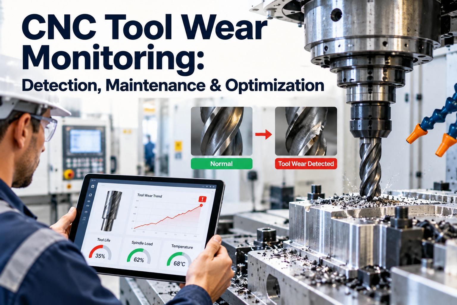
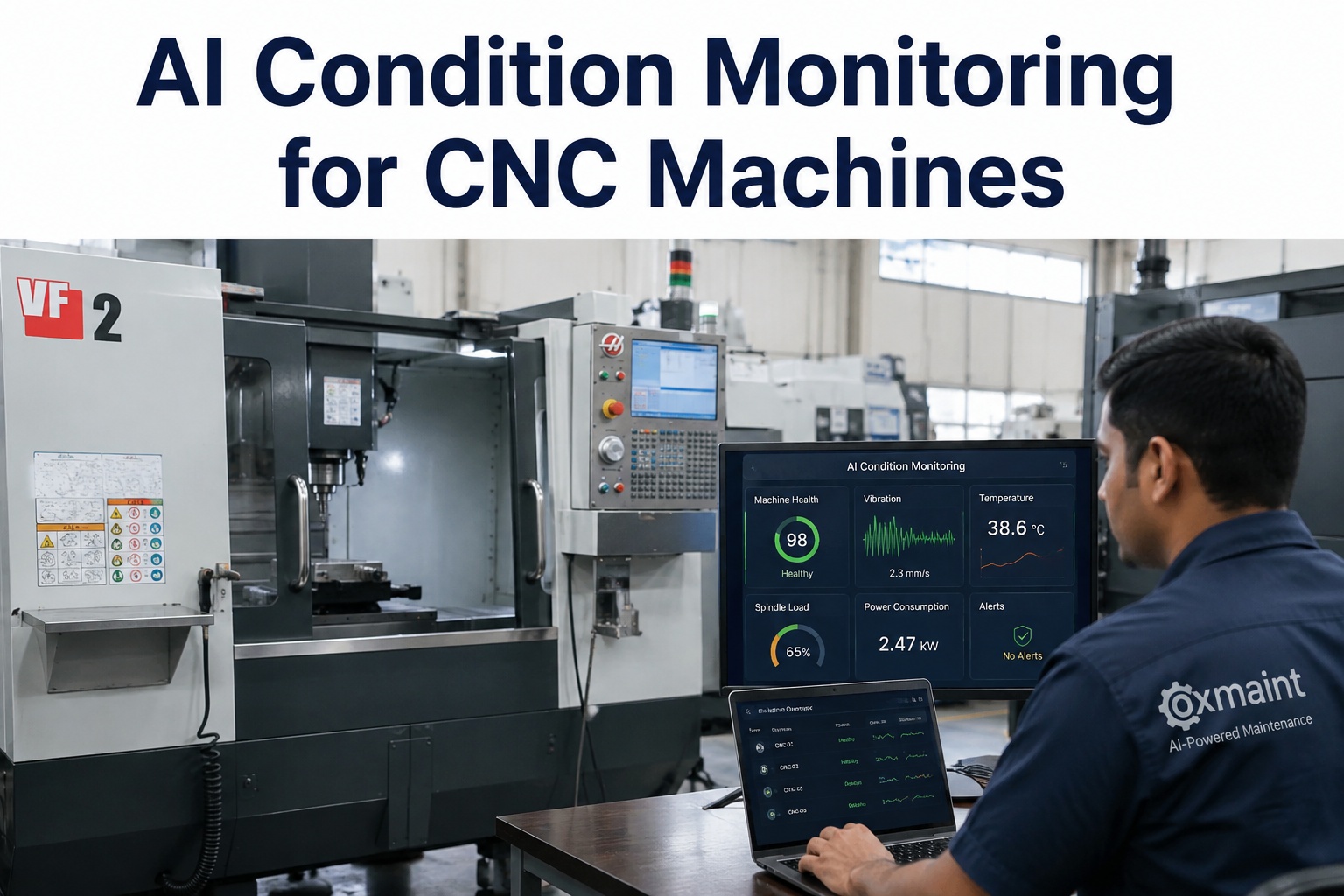
A cutting edge doesn't fail all at once — it wears slowly, predictably, and then falls off a cliff. Run a tool past that point and you scrap the part, gouge the finish, and risk the spindle. Catch the wear as it ramps and you change the edge on your schedule, not the machine's. This guide covers CNC tool wear monitoring — the wear patterns, the detection methods, and how OXMAINT AI, the AI-powered maintenance CMMS, turns a wear signal into a tool-change work order.
CNC Machining · Tool Condition Monitoring · Maintenance & Optimization · 2026
CNC Tool Wear Monitoring: Detection, Maintenance & Optimization
A tool run one pass too long scraps the part, wrecks the surface finish and can load the spindle until something lets go. OXMAINT AI, the AI-powered CMMS and maintenance management software, trends the wear signal, flags the edge nearing its limit, and raises a tool-change work order before the defect reaches the part — so tool life is managed, not guessed.
1Sense wear
→
2Trend to limit
→
3Alert
→
4Change & log
THE TOOL-WEAR CURVE
break-insteady-stateaccelerated
Change the tool before stage III — where thermal cracks and deformation run away
VB 0.3 mm
common roughing flank-wear change trigger (ISO 8685-1)
3 stages
break-in → steady-state → accelerated wear
VTⁿ=C
Taylor's tool-life relationship for speed vs life
4 methods
load, acoustic, vibration, probe — direct or indirect
How A Cutting Edge Actually Wears
Tool wear isn't one thing — it's a handful of distinct mechanisms, each with its own cause and its own tell. Knowing which one you're seeing decides the fix: a speed change, a coolant change, or just a timelier tool swap. You can book a demo to see wear tracking in OXMAINT AI.
□Flank wear (VB)
A wear land on the relief face from rubbing against the machined surface. The primary, most measurable wear — VB is the standard tool-change metric.
Cause: abrasion, adhesion, heat
▢Crater wear (KT)
A depression on the rake face where the chip slides, deepest at the hottest point of the tool-chip interface. Weakens the edge over time.
Cause: diffusion, high interface temperature
▲Built-up edge
Workpiece material welds onto the edge, then sloughs off — shifting dimensions and tearing the finish as it builds and breaks away.
Cause: adhesion at low speed / high affinity
◇Chipping & fracture
Fragments break from the edge, often at an existing crack — a step change, not a gradual ramp, so it needs a fast-responding sensor to catch.
Cause: mechanical shock, thermal fatigue
Four Ways To See The Wear
You can't easily watch the edge mid-cut, so monitoring is mostly indirect — inferring wear from force, sound, vibration or a periodic measurement. Each method has a sweet spot and a blind spot, and the strongest programs combine two. You can start free and trend tool signals in OXMAINT AI.
| Method | How it works | Strength | Blind spot |
| Spindle load / current |
Rising cutting force shows as higher drive current or torque as flank wear grows |
Zero extra hardware if the drive exposes it — trend it against a baseline |
Misses chipping, which is a step change rather than a ramp |
| Acoustic emission |
Piezo sensors pick up high-frequency bursts from the tool-chip interface |
Catches flank wear, chipping and finish loss; models can estimate VB |
Needs added sensors and signal processing per spindle |
| Vibration |
Accelerometers detect chatter and edge fracture; also a load proxy |
Strong on chatter and sudden fracture |
Noisy; needs filtering to separate wear from process vibration |
| Touch probe |
Measures tool length and diameter against a datum between cuts |
Direct geometric check to about micron repeatability |
Verifies geometry only — misses finish loss and small chips; adds cycle time |
Indirect methods infer wear from the process; a probe measures it directly between cuts. Scroll sideways on mobile to see every column.
The Signal Was Climbing For Ten Parts. Nobody Was Watching It.
Spindle load creeps up as the edge wears — a clear ramp if someone trends it, invisible if the number only lives on the controller. Baselined and trended, that climb raises a tool-change work order before the part goes out of tolerance.
When To Change The Tool — And Why It Pays
The change point is a balance. Pull the tool too early and you waste edge life and spend on tooling; run it too long and you scrap parts and risk the spindle. Two ideas anchor the decision.
The VB limit
Flank wear land width (VB) is the usual change criterion — a common roughing trigger is around 0.3 mm per ISO 8685-1, with a tighter limit for finishing where surface quality matters. The tool changes when trended VB reaches the limit, not when a part already failed.
Taylor's tool life
Taylor's equation, VTⁿ=C, ties cutting speed to tool life: push speed up and life drops sharply. It's why "run it faster" and "make tools last" pull against each other — and why the optimization is a deliberate choice, not a default.
From Wear Signal To Work Order
Monitoring only pays off when the signal drives an action and leaves a record. OXMAINT AI baselines each tool, watches the trend, and turns a limit crossing into a scheduled change logged against the machine, and you can book a demo to see the tool-change workflow in OXMAINT AI.
01
Baseline
A healthy signal is learned from the first good parts, setting the normal band for each tool and operation.
02
Trend
Spindle load, vibration or probe readings are tracked part over part, filtering out spikes to see the real ramp.
03
Alert
An early warning fires as the trend approaches the limit, with a harder trigger at the change threshold.
04
Change & log
A tool-change work order is raised and, once done, logged against the machine — building a tool-life history.
What OXMAINT AI Adds To The Machine
A controller shows the current reading; the CMMS gives it memory, a limit and an owner. OXMAINT AI ties tool monitoring to work orders, machine history and the PM schedule, and you can start free and connect your CNC assets in OXMAINT AI.
◉
Signal Trending & Alerts
Spindle-load and sensor readings trended against a baseline, with early-warning and change-point alerts.
◉
Tool-Change Work Orders
A limit crossing raises a prioritized work order so the swap is scheduled, not a surprise mid-run.
◉
Tool-Life History
Every change logs against the machine and tool, so actual life per operation becomes data you can tune.
◉
Spindle & Machine PM
Tool monitoring sits alongside spindle, way and coolant PMs on one machine asset record.
◉
Defect Linkage
Scrap and finish issues tie back to tool condition, so recurring wear-driven defects surface fast.
◉
Uptime Visibility
Unplanned tool-related stoppages trend by machine, pointing to the worst offenders for optimization.
“
We changed cutting edges on a fixed part count — which meant tossing edges with life left on easy jobs and running others until a part went out of tolerance on the hard ones. Trending spindle load against a baseline per operation and letting it raise the change order turned tool life into something we actually measure. Scrap from worn tools dropped, and we stopped throwing away good edges on a calendar.
CNC Manufacturing Engineer · Precision Machine Shop
Frequently Asked Questions
What is flank wear and why does VB matter?
Flank wear is the wear land that forms on the relief face of the tool from rubbing against the machined surface. Its width, VB, is the standard way to quantify wear and set the change point — a common roughing trigger is around 0.3 mm under ISO 8685-1, tighter for finishing where surface quality is critical. Trending toward VB beats changing after a part fails.
Book a demo to see wear trending in OXMAINT AI.
What are the stages of the tool-wear curve?
Three: an initial break-in where a new edge beds in and wear rises quickly, a steady-state stage where wear grows at a roughly constant rate, and an accelerated stage where thermal cracks and deformation make wear run away. The goal is to change the tool late in steady-state, before it enters the accelerated stage.
Which monitoring method is best?
It depends on the blind spot you can't afford. Spindle-load trending is free if the drive exposes it but misses sudden chipping; acoustic emission and vibration catch chipping and finish loss but need added sensors; a touch probe measures geometry directly but misses finish and small chips and adds cycle time. Strong programs pair an always-on indirect method with a periodic probe check.
How does Taylor's equation affect tool life?
Taylor's tool-life equation, VTⁿ=C, links cutting speed (V) to tool life (T): raising speed shortens life steeply because the exponent compounds the effect. It's the reason faster cycle times and longer tool life trade off against each other, and why the change interval and the speed are an optimization decision rather than a fixed rule.
How does a CMMS help with tool wear?
It gives the signal memory and consequence: baseline the healthy reading, trend it part over part, alert as it approaches the limit, and raise a tool-change work order that logs against the machine. Over time that builds a real tool-life history per operation and ties scrap and finish defects back to tool condition.
Start free and manage tool life in OXMAINT AI.
Change The Tool On Your Schedule, Not The Part's.
Run CNC tool wear monitoring on the OXMAINT AI maintenance management software — signal trending against a baseline, early-warning and change-point alerts, tool-change work orders, and a tool-life history that links wear to scrap and uptime. Catch the ramp before the edge falls off the cliff.