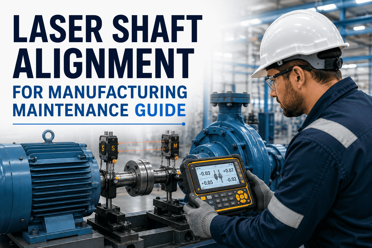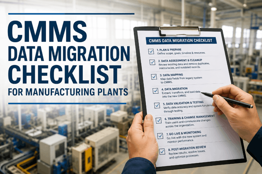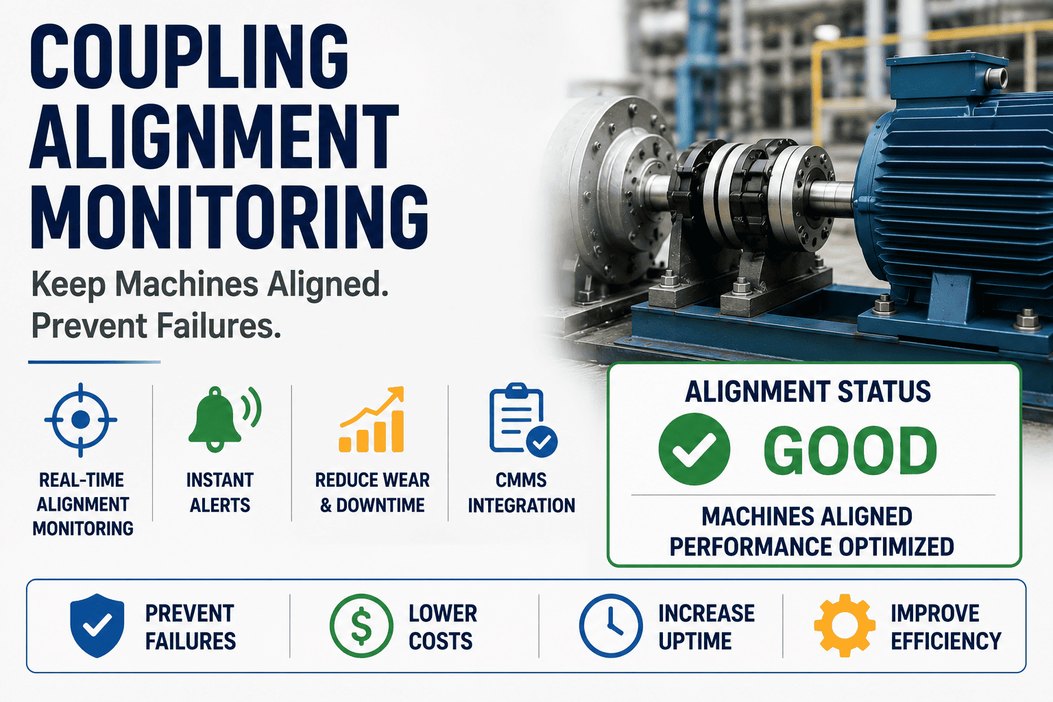
Coupling alignment is one of those quiet maintenance disciplines that separates a reliable plant from a reactive one — when shafts drift beyond a few thousandths of an inch, vibration climbs, bearings overheat, and seals begin to weep long before a work order is ever written. In most manufacturing facilities, alignment degrades not from a single event but from the slow accumulation of thermal cycles, foundation settling, pipe strain, and vibration that quietly nudges a precision coupling out of tolerance. A modern CMMS changes that equation by turning alignment from an episodic task into a monitored condition — with laser readings, tolerance standards, soft-foot checks, and thermal-growth compensation all logged, trended, and triggered automatically. If you want to see how that workflow looks in practice, you can Start Free Trial and explore the alignment monitoring module firsthand.
How long since you verified your couplings were actually within tolerance?
Shaft alignment drifts as foundations settle, temperature cycles, and vibration accumulates — turning a precision coupling into a failure point without warning. A CMMS converts alignment from a calendar guess into a monitored, trended condition.
Good alignment quietly becomes bad alignment
A coupling aligned to 0.02 mm during a shutdown can exceed 0.10 mm within months — not from negligence, but from forces every rotating asset faces every shift.
A 180-asset chemical plant spending roughly $42K per year on coupling-related seal and bearing repairs implemented quarterly laser alignment monitoring tied to their CMMS. Within 12 months, coupling-driven work orders fell by 38% and mean time between seal failures on hot-water pumps doubled from 9 to 18 months — a payback under one fiscal quarter on the monitoring investment alone.
A tiered monitoring schedule by asset criticality
Not every coupling needs the same attention. A risk-based interval — driven by speed, torque, temperature swing, and downtime cost — concentrates precision work where it pays back hardest.
Critical & high-speed
Turbines, high-RPM pumps, and any coupling on a single-point-of-failure asset. Laser verification every 30 days, vibration trend reviewed weekly.
- Speeds above 1800 RPM
- Downtime cost above $5K/hr
- Forced-lubrication couplings
Process & temperature-cycling
Hot pumps, blowers, and compressors where thermal growth and pipe strain matter. Laser alignment every 90 days, with hot-alignment verification after first start-up.
- Operating temp above 60°C
- Variable-load duty cycles
- Long-span piping attached
General duty & backup
Fans, agitators, low-speed drives, and redundant equipment. Dial-indicator sweep or laser every 6 months, with a vibration-route trigger for exceptions.
- Speeds below 1200 RPM
- Standby / backup assets
- Non-critical auxiliaries
Choosing the right measurement method
Both tools have a place in a precision-maintenance program. The question is which one fits the coupling, the access constraints, and the data you need to capture in the CMMS.
| Criterion | Laser alignment system | Dial indicator sweep |
|---|---|---|
| Typical accuracy | 0.001 mm resolution, repeatable | 0.01 mm — operator-dependent |
| Setup time per coupling | 8–15 minutes | 30–60 minutes |
| Soft-foot detection | Built-in measurement module | Manual shimming required |
| Thermal growth compensation | Pre-loaded target values per asset | Calculated and entered manually |
| Digital record into CMMS | Direct export of readings and reports | Manual data entry from log sheet |
| Best fit | Critical, high-speed, high-temp assets | Low-speed, accessible, backup assets |
Compensating for the alignment that disappears at temperature
A coupling aligned perfectly cold can run misaligned hot. Thermal growth is predictable — and once the formula lives in your CMMS, every start-up starts in tolerance.
Why it matters
A pump foot 400 mm from the centerline running 60°C above ambient grows roughly 0.29 mm vertically. Without hot-alignment compensation, that coupling runs out of tolerance from the moment it reaches operating temperature — even though the cold alignment was perfect.
If the cold alignment is perfect, the running alignment is perfect.
Thermal growth, pipe strain, and dynamic torque can shift a shaft 0.05–0.15 mm between cold and hot states — enough to exceed ANSI/ASA tolerance on most couplings.
What a complete alignment record should capture
An alignment reading without context is just a number. The CMMS record is what lets you trend, audit, and predict — and it is what turns a one-time measurement into a monitored condition.
Asset & coupling identity
Coupling type, size, manufacturer, model, and the connected driver/driven asset pair. Without this, readings cannot be benchmarked against the correct tolerance class.
Tolerance standard applied
ANSI/ASA S2.75 or OEM-specified angular and offset limits, plus the asset's classification (general, special, high-speed). Recorded so audits can verify the right standard was used.
Soft-foot findings
Pre-correction soft-foot readings on each foot, the correction applied (shim thickness, machined base), and post-correction verification. Soft foot masks real misalignment.
Thermal growth target
Calculated or measured thermal offset used for hot-alignment, the formula inputs, and whether the final reading was cold-to-hot compensated.
Final readings & pass/fail
Vertical offset, horizontal offset, angularity in both planes, and a clear pass/fail against tolerance. Timestamped, technician-verified, photo-attached.
Next-due trigger
Next alignment date based on the asset's criticality tier, plus an exception trigger if vibration trend on that point exceeds baseline by 20%.
What monitored alignment delivers on the floor
"We tied laser alignment results directly into each asset record and cut coupling-related vibration alarms by a third in the first quarter. The trend chart is what sold reliability to operations."
"Switching from paper alignment sheets to a CMMS-tracked record meant we finally caught the three pumps that kept drifting every thermal cycle. Seal spend dropped noticeably within a year."
Turn alignment into a trended condition, not a calendar guess
Set tolerance standards, capture laser readings, log soft-foot corrections, and trigger the next alignment automatically — all inside one CMMS.
Coupling alignment monitoring — answered
What tolerance standard should I use for coupling alignment?
For most manufacturing applications, ANSI/ASA S2.75 provides angular and offset limits by coupling type and speed. For high-speed or special-purpose machinery, follow the OEM specification or API 686. The CMMS should store the standard against each asset so the technician sees the correct target on every work order.
How often should coupling alignment be checked?
Critical and high-speed assets typically warrant monthly laser verification, process and temperature-cycling assets quarterly, and general-duty or backup equipment semi-annually. The right cadence also depends on vibration trends — if vibration at the coupling point rises 20% above baseline, trigger an out-of-schedule check regardless of the calendar.
What is soft foot and why does it matter?
Soft foot is a condition where one or more machine feet do not sit flat on the baseplate, usually from pipe strain, foundation distortion, or incorrect shimming. It introduces shaft strain that masks true misalignment and can spring the frame when bolts are tightened. Always measure and correct soft foot before taking final alignment readings. To see the workflow, you can Book a Demo and we will walk through it on your asset list.
How does thermal growth affect coupling alignment?
As a machine heats up, its centerline rises by a predictable amount — roughly 0.012 mm per meter per degree Celsius for steel. A pump running 60°C above ambient with a 400 mm centerline height grows about 0.29 mm vertically. Without compensating for that growth in the cold-alignment target, the coupling runs out of tolerance the moment it reaches operating temperature.
Can a CMMS really improve alignment outcomes?
Yes — by capturing every reading against the asset, trending the values, and auto-triggering the next check based on criticality or vibration data. Instead of a paper sheet filed in a binder, each alignment becomes a data point in a trend that lets you spot the assets that keep drifting, schedule corrections before failure, and audit compliance with tolerance standards. You can Start Free Trial to test the full record-keeping workflow on your own assets.
Start monitoring coupling alignment the way precision plants do
Capture laser readings, log soft-foot corrections, apply thermal-growth targets, and trigger the next alignment automatically — all in one CMMS built for manufacturing reliability.
Free 14-day trial · No credit card