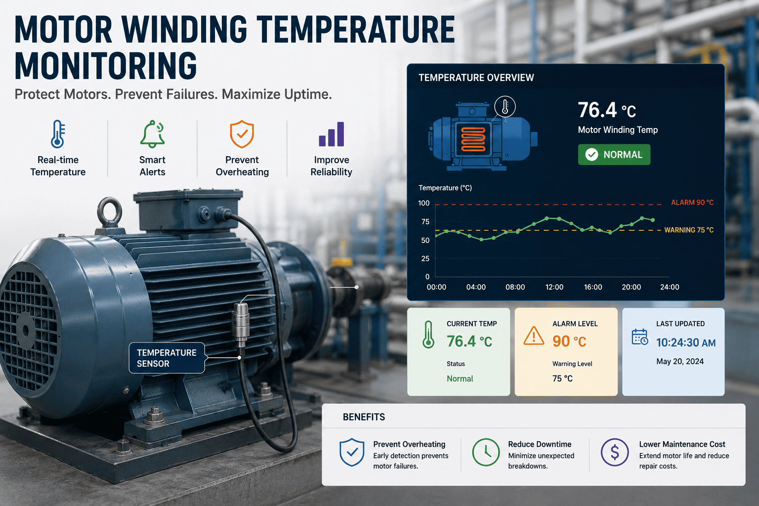
Motor winding temperature is the single most reliable predictor of motor life — the industry-accepted rule is that every 10°C rise above the insulation class rating halves expected winding life. For a manufacturing plant running dozens or hundreds of motors, that translates directly into unplanned downtime, rewinding costs, and lost production. This guide breaks down motor winding temperature monitoring for manufacturing plants: PT100/RTD placement, class-based thermal limits, common overheating causes, thermal imaging supplements, and CMMS alert configuration. Want to put it into practice immediately? Start Free Trial and trend winding temperatures across your asset register today.
Are you waiting for a motor to fail before you read its temperature?
A single 10°C overshoot beyond a motor's insulation class rating cuts winding life in half. Continuous motor winding temperature monitoring — paired with the right PT100 placement and CMMS alert thresholds — catches thermal stress weeks before a rewind becomes unavoidable.
Why winding temperature is the leading indicator of motor life
Industry studies put the average cost of an unplanned motor outage in a continuous-process plant at $12,000–$60,000 per hour. The thermal signature of the winding is the earliest, most quantitative signal you have.
A mid-sized plant running 180 motors can lose $42,000 a year in unplanned downtime to thermal failures that a $40-per-point RTD network would have flagged two to three weeks in advance.
— Worked example based on typical 75–250 kW motor populations in discrete manufacturingPT100 and RTD placement rules that actually protect the winding
A PT100 (RTD Pt-100) sensor only reflects winding temperature accurately when it is embedded in the right slot and properly routed. Three critical placement decisions make or break the reading.
Embed the RTD in the hottest stator slot
Place at least one PT100 in the slot positioned at the top-center of the stator core — the convective hot zone where winding temperature peaks. A second sensor should sit on the opposite drive-end side to capture asymmetry from rotor-driven heating.
Use three sensors for motors above 150 kW
IEC 60034-11 and most OEM specs call for three RTDs in the winding for medium-voltage and large frames: one hottest-slot, one line-end (where harmonics and phase imbalance concentrate losses), and one neutral-end for comparison.
Route leads away from the rotor air gap
Sensor leads must exit the frame through a sealed gland, kept clear of the rotor air gap and any rotating cooling fan. Vibration chafing at the lead exit is the most common reason a PT100 fails silently — always wire the sensor to a CMMS-monitored input so a broken loop triggers an alert, not a blind spot.
Class-based temperature limits and alarm thresholds
Every motor's nameplate insulation class defines a maximum winding temperature. Alarm thresholds should be set 10–15°C below that ceiling so operators get a window to act before the insulation begins to degrade.
| Insulation class | Max winding temp (rated) | Class temp rise (resistance) | Warning alarm | Critical / trip |
|---|---|---|---|---|
| Class A (105°C) | 105°C | 60°C | 90°C | 100°C |
| Class E (120°C) | 120°C | 75°C | 105°C | 115°C |
| Class B (130°C) | 130°C | 80°C | 115°C | 125°C |
| Class F (155°C) | 155°C | 105°C | 140°C | 150°C |
| Class H (180°C) | 180°C | 125°C | 165°C | 175°C |
Critical = Tmax − 5°C A 15°C warning window typically gives maintenance teams 2–6 hours of lead time on thermally overloaded motors.
What actually overheats a motor winding
Winding temperature rarely spikes for a single reason. The six causes below account for the majority of thermal events seen in manufacturing plants — each produces a characteristic trend shape in a CMMS.
Overload and sustained over-current
A motor pushed beyond its nameplate service factor heats the stator proportionally to I²R losses. A 10% overload can push winding temperature 15–20°C above rated within minutes, often before a thermal overload relay trips.
Under- and over-voltage
Voltage deviation beyond ±5% of rated raises copper and core losses. Under-voltage forces higher current to deliver the same shaft power; over-voltage saturates the core and spikes iron losses — both end up as winding heat.
Blocked or degraded cooling
A clogged TEFC fin pack, failed forced-ventilation fan, or dust-loaded screen reduces airflow so the winding cannot shed heat. Ambient temperature rise compounds the effect: every 1°C of hotter intake air lifts winding temperature roughly 1°C.
Harmonics and phase unbalance
A 3% voltage unbalance can raise winding temperature by 25°C. Harmonics from VFDs without proper filtering add high-frequency losses that show up as a slow upward drift in the trend, even at constant load.
Mechanical friction and misalignment
Worn bearings, belt over-tension, or shaft misalignment drag the rotor, increasing current draw and rotor heating that conducts back into the stator. Look for a rising trend that tracks a simultaneous vibration alarm.
Frequent starts and high duty cycle
Starting current runs 5–7× rated, dumping heat into the winding in 2–8 seconds. Repeated starts without a cool-down interval accumulate thermal stress that an RTD only catches if it samples at 1 Hz or faster.
Configuring CMMS alerts for winding temperature trending
A PT100 sensor without a CMMS is just a thermometer. Real protection comes from trending the signal, setting tiered alarms, and routing work orders automatically when thresholds are breached.
Wire RTDs to a PLC or IoT gateway sampling at 1 Hz
Sample once per second so the system catches the rapid thermal transients that happen during motor starts, load changes, and stall events. Publish values over Modbus, OPC UA, or MQTT to your CMMS data engine.
Map each sensor to an asset record with class-based limits
Tag every RTD input against the motor's asset ID in the CMMS, then attach the insulation class, ambient reference, warning, and critical thresholds so the system knows what "normal" looks like for that specific winding.
Set three-tier alerts: advisory, warning, critical
Advisory at 80% of headroom, warning at 90%, critical at 95% of the class limit. Advisory generates a notification only, warning creates a planned work order, critical triggers an immediate work order plus an operator alarm in the HMI.
Trend weekly and trigger PdM on rate-of-rise
Beyond absolute thresholds, monitor the slope of the trend. A winding that climbs 3°C/week under constant load signals insulation breakdown or contamination long before it ever crosses the critical line — schedule a predictive inspection, not a shutdown.
Without winding temperature monitoring
- Motors fail mid-shift with no thermal warning
- Rewinds cost $2,500–$15,000 per incident
- Production downtime averages 4–18 hours
- Insulation damage discovered only at teardown
With CMMS-trended RTD monitoring
- Warnings surface 2–3 weeks before failure
- Work orders auto-generated at threshold breach
- Planned maintenance replaces emergency rewinds
- Insulation life extended 20–40% on protected motors
Stop guessing about winding health — start trending it.
OxMaint maps every PT100 and RTD to an asset record, auto-creates thermal work orders, and gives your team a real-time winding temperature dashboard across the whole plant.
Motor winding temperature monitoring — answered
What is the best sensor for motor winding temperature monitoring?
For most manufacturing motors, a PT100 (Pt-100 platinum RTD) embedded in the stator winding offers the best balance of accuracy (±0.3°C at 100°C), long-term stability, and CMMS compatibility. Use three RTDs for motors above 150 kW — one in the hottest slot, one at the line end, and one at the neutral end — so you can detect phase-to-phase thermal asymmetry.
Where exactly should the PT100 be placed in the winding?
Place the primary RTD in the stator slot at the top-center of the core, where natural convection makes the winding run hottest. Route the leads through a sealed gland away from the rotor air gap and cooling fan to avoid vibration chafing. For VFD-driven motors, add a second sensor at the line end where harmonic losses concentrate. You can Book a Demo and we'll walk you through a placement diagram for your specific frame sizes.
How does CMMS alert configuration work for winding temperature?
Each RTD input is mapped to a motor asset record in the CMMS, with the insulation class and ambient reference attached. The system then evaluates the live temperature against three tiers — advisory at 80% of headroom, warning at 90%, critical at 95% of the class limit. Warning triggers an auto-generated work order; critical triggers an immediate work order plus an HMI alarm. Most teams also add a rate-of-rise rule (e.g. 3°C/week) to catch slow degradation before absolute limits are reached.
Can thermal imaging replace embedded RTDs?
No — thermal imaging is a powerful supplement, not a replacement. A thermal camera reads surface temperatures at the motor frame, bearings, and terminal box, which makes it excellent for spotting blocked cooling, hot connections, and bearing faults during routine rounds. But it cannot see the internal stator winding temperature directly, and it only captures a snapshot. Embedded RTDs give continuous, internal readings that feed a CMMS trend; thermal imaging fills the diagnostic gaps in between.
How much can a plant save by monitoring motor winding temperature?
A 180-asset plant spending roughly $42,000 a year on unplanned motor failures and rewinds typically recovers the cost of an RTD-plus-CMMS deployment within 4–8 months. Most sites see a 20–40% extension in insulation life on protected motors and a 50%+ drop in emergency rewind orders. You can model your own numbers — Start Free Trial and import your asset register to see the trending dashboard live.
See your motor winding temperatures in one dashboard — before they fail.
Connect your PT100 and RTD sensors, set class-based alarm thresholds, and let OxMaint auto-generate thermal work orders across every motor in your plant.
Free 14-day trial · No credit card