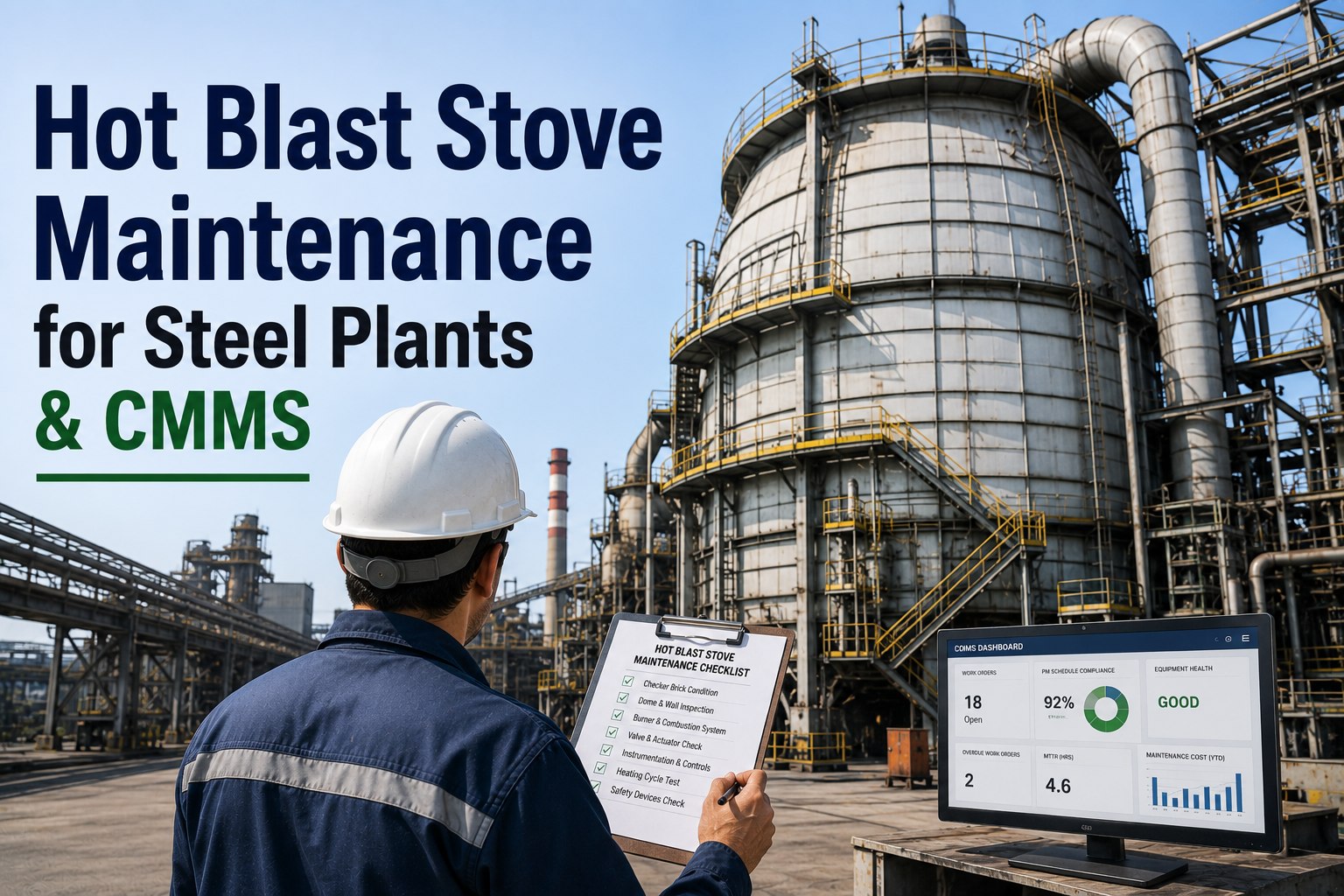
Hot-blast stove valves work in some of the harshest conditions in an integrated steel plant. Every changeover loads water-cooled discs, seats, stems and actuators with heat, pressure and cycling stress, and one cooling-water leak or seat bypass can become a stove trip, a drop in blast temperature or a forced furnace stop. This guide covers valve inspections, campaign hours, temperature trends, actuator condition and corrective work, and shows how a steel plant CMMS keeps the history of every valve in one place.
Blast Furnace Stove Valve Maintenance Guide for Steel Plant Reliability
Stove valves rarely fail without warning. Falling cooling-water flow, slower strokes and creeping shell temperatures show up first, then get lost between rounds sheets and memory. Oxmaint turns those signals into scheduled inspections, trended readings and corrective work orders for each valve.
Why Stove Valves Need Their Own Maintenance Program
A blast furnace needs a steady supply of hot blast, and the stoves deliver it by cycling between heating and blowing. The valves around each stove make that cycle possible. They also take the stress of it, hundreds of times a month, at blast temperatures commonly quoted between 1,150 and 1,250 °C at the hot blast valve.
Most stove valve programs fail for a simple reason: the checks exist, but the readings are not trended per valve, so a slow decline looks like normal variation until the day it is not.
The Stove Valve Map: What Fails and What to Record
| Valve | Duty | Typical warning signs | What to record |
|---|---|---|---|
| Hot blast valve | Passes or isolates blast at the stove outlet, usually water cooled | Falling cooling-water flow, shell hot spots, seat bypass, slow stroke | Outlet flow, inlet and outlet water temperature, stroke time, cycle count |
| Cold blast valve | Separates the stove from the cold blast main | Leakage, sticking, actuator lag | Stroke time, leak checks, position feedback |
| Chimney valve | Opens to the stack on gas, closed on blast | Dust-clogged seats, uneven seating, flue gas leakage | Seat inspection notes, stroke time, seal condition |
| Burner shutoff valve | Isolates the burner from the stove on blast, often water cooled | Distortion, leaking gas, cooling circuit faults | Water flow, inspection photos, leak test result |
| Gas and combustion air valves | Regulate and shut off fuel and air to the burner | Slow closure, internal leakage, linkage wear | Safety test results, stroke time, calibration dates |
| Cold blast mixer valve | Trims hot blast temperature | Hunting, sticking, poor temperature control | Valve position against blast temperature trend |
| Bleeder and relief valves | Release pressure and protect against overpressure | Failure to reseat, seat damage | Test dates, set pressure, inspection notes |
What a Real Valve Failure Teaches About Monitoring
A published failure investigation looked at a water-cooled gate-type hot blast valve that failed after roughly one year. The pattern is a useful template for any stove.
- The refractory was intact, so the cause was not simply overheating. It was fatigue at a weld.
- The clearest warning was a trend in cooling-water flow, available weeks ahead.
- Weld repair quality is a maintenance record, not only a workshop detail.
The lesson for planners: log outlet flow for each water-cooled valve at a fixed interval, set an alert against that valve's own baseline, and treat a sustained decline as a corrective work order, not a note on the rounds sheet.
Inspection Plan by Frequency
Split checks by how quickly a condition can change. Operations rounds catch fast problems, scheduled PMs trend slow ones, and shutdown windows cover what cannot be seen on blast.
Each shift or round
- Visual check for leaks, steam or water at valve bodies
- Actuator and hydraulic line condition
- Abnormal noise or vibration during changeover
- Gas leak indications near burner valves
Monthly or quarterly
- Cooling-water outlet flow and temperature per valve
- Stroke time against baseline
- Shell temperature scan of valve bodies
- Limit switch and position feedback check
Planned shutdown
- Disc and seat condition, sealing faces
- Cooling jacket pressure test
- Weld inspection at known stress points
- Packing, seals, stem and actuator overhaul
Put Every Stove Valve on a Schedule You Can Trust
Set up each valve as an asset, attach its inspection checklist and let Oxmaint raise the work when readings or hours say it is due.
Campaign Hours and Cycle Counts
Calendar PMs treat a valve that cycled lightly the same as one that cycled constantly. Usage-based triggers fix that.
| Counter | Why it matters | How to use it |
|---|---|---|
| Cycle count per valve | Fatigue cracking follows cycles, not months | Trigger seat, weld and actuator inspection at a cycle threshold set with the OEM |
| Hours on blast per stove | Shows thermal exposure of valves and refractory | Compare valves on the same stove and across stoves |
| Hours since last overhaul | Defines the repair interval actually achieved | Feed back into the next shutdown scope |
| Campaign start and reline dates | Valve wear should be read against campaign age | Align valve overhauls with stove outage windows |
Record the hours and counts on the asset itself so the next planner can see how long a valve really lasted and why it came out.
Temperature Trends That Warn Before a Valve Fails
Water is the sensitive point. Some designs avoid water cooling in the hot blast valve because a leak can put moisture into the blast, which is harmful to the furnace. If your valves are water cooled, flow and temperature trends are not optional.
Actuator Condition: The Part Operators Notice Last
Actuators are easy to overlook until a valve will not move. Track a few numbers on each and compare them with the valve's own commissioning baseline.
Run to failure
- Stroke time noticed only when changeover slows
- Hydraulic oil changed on a fixed date regardless of condition
- Limit switches adjusted ad hoc
- Failures explained verbally, not recorded
Condition tracked
- Stroke time logged and trended per valve
- Oil cleanliness and leaks recorded at each PM
- Limit switch and feedback checks on a checklist
- Every failure coded and linked to the asset
Gas shutoff and regulating valves also carry a safety role, and some systems are designed to fail closed on loss of power or hydraulics. Test those functions on the interval set by your safety procedures and OEM, and keep the results with the valve record.
Corrective Maintenance Workflow for Stove Valves
Spares and Weld Repair Records
Because weld quality sat at the root of the published failure, repair history deserves the same care as the part itself.
- Keep critical spares for each valve type: discs, seats, stems, seals, actuator components and hydraulic hoses.
- Link spares to the valves that use them, so a shortage is visible before a shutdown.
- Attach weld procedure, inspection results and post-weld heat treatment confirmation to any cooling jacket repair.
- Record refurbished versus new components, with their service life, to guide future repair-or-replace decisions.
Planning the Stove Outage Scope
Stove outages are scarce, so valve work has to be ready before the window opens. Build the scope from open findings, not from memory.
- Pull open findings and trend alerts for every valve on the stove
- Confirm discs, seats, seals and actuator parts are in stock or on order
- Book cranes, scaffolding and welders with qualified procedures
- Record as-found condition and photos before any repair
- Pressure test cooling jackets and log results against the last test
- Capture new baselines for flow, temperature and stroke time
- Watch the first campaign weeks for flow or temperature drift
- Close work orders with failure codes and parts used
- Feed findings into the next outage scope
Safety and Compliance Records Around Stove Valves
Stove areas involve blast furnace gas, high temperatures and pressurized systems, so documentation is part of the job, not an afterthought.
- Link isolation, lockout and gas-free permits to the work order for each valve task.
- Keep test records for gas shutoff and fail-closed functions with date, result and tester.
- Store pressure test and weld inspection reports on the valve record.
- Track technician competence for hot work, confined space and gas-area entry where your site requires it.
Follow your site procedures and the equipment manufacturer's instructions. The software holds the evidence, but the standards come from your safety team and the OEM.
Common Mistakes in Stove Valve Maintenance
A 90-Day Rollout for One Blast Furnace
How Oxmaint Supports Stove Valve Reliability
KPIs to Review Every Month
| KPI | What it tells you |
|---|---|
| Stove-related trips and delays | Whether valve work is protecting blast delivery |
| Mean time between failures by valve type | Which valves deserve redesign or tighter intervals |
| Planned versus corrective hours | How much valve work is still reactive |
| Cooling-flow deviations open | How many early warnings are waiting for action |
| Stroke time drift | Actuator health across the fleet of valves |
| Repeat failures on the same valve | Whether root causes are being fixed or patched |
Frequently Asked Questions
Keep the Blast Steady by Keeping Every Valve Visible
Give each stove valve a record, a schedule and a trend line. Oxmaint helps your team catch cooling losses, slow actuators and repeat failures before they cost a stove cycle.