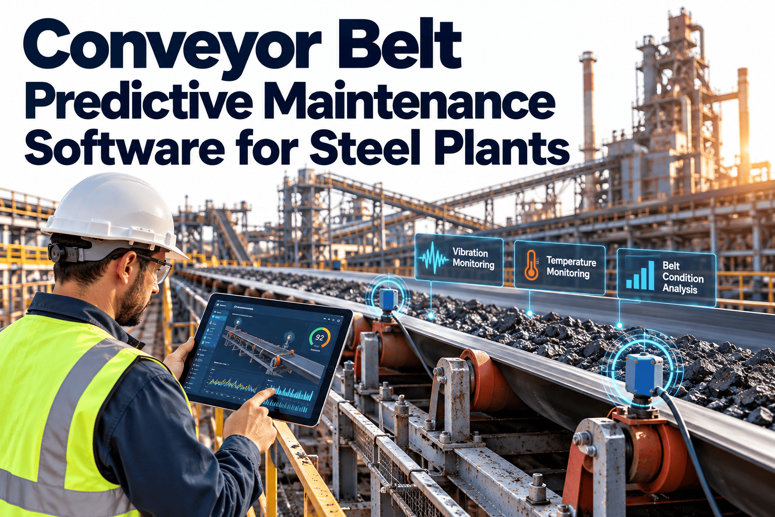
Steel plant conveyors, bearings, and rollers operate in conditions that would destroy most industrial equipment within months—ambient temperatures exceeding 150°F near furnaces and casters, fine iron oxide dust that penetrates every seal, water and scale contamination from descaling sprays, and shock loads from multi-ton slabs and coils landing on roller tables at full production speed. These components are not glamorous. They don't appear on the plant manager's dashboard the way the rolling mill main drive or the blast furnace control system does. But they are the circulatory system of the entire operation—moving raw materials, intermediate products, and finished steel between every process step from the ore yard to the shipping bay. When a conveyor bearing seizes on the hot strip mill run-out table, the entire mill stops.
15,000–40,000
Bearings
Conveyor idlers, roller tables, transfer cars, cooling beds, coil transport, and material handling — each operating in heat, dust, water, and shock conditions
3,000–8,000
Rollers & Idlers
Run-out tables, approach tables, roller hearth furnaces, cooling beds, coil conveyors — surface degradation, bearing failure, and thermal distortion are primary failure modes
50–200
Conveyor Systems
Belt conveyors, apron feeders, screw conveyors, vibratory feeders, and bucket elevators moving ore, coal, flux, scale, scrap, and finished products
$4M–$12M
Annual Maintenance Spend
Bearing replacements, roller resurfacing, conveyor belt repairs, lubrication, and unplanned failure response across a typical integrated mill
Why Steel Plant Conditions Destroy Bearings and Rollers
Standard industrial bearing life calculations assume clean, temperature-controlled, properly lubricated environments. Steel plant bearings operate in conditions that reduce theoretical bearing life by 60–90%. Understanding the specific degradation mechanisms is essential for selecting the right monitoring technologies and interpreting the data correctly. Facilities that sign up to track their bearing and roller maintenance history on a centralized platform build the failure-mode database that makes condition monitoring actionable.
Bearings near the caster, run-out table, and reheating furnace operate at 150–300°F ambient, with radiant heat spikes exceeding 500°F during slab passage. Standard lithium grease breaks down above 250°F, losing viscosity and load-carrying capacity. Even high-temperature greases lose 50% of their effective life for every 25°F above their rated continuous temperature.
Bearing impact: Lubricant degradation → metal-to-metal contact → accelerated spalling → catastrophic seizure in weeks rather than months
Fine mill scale and iron oxide particles are pervasive throughout steel plants—especially near descaling operations, scarfing stations, and the run-out table. Particles as small as 5 microns penetrate bearing seals and act as an abrasive lapping compound, accelerating wear on races and rolling elements. Contaminated lubricant becomes a grinding paste rather than a protective film.
Bearing impact: Abrasive wear accelerates surface degradation 3–5x → reduced bearing life from years to months in severe contamination zones
Water & Coolant Contamination
Descaling sprays at 2,000+ PSI, laminar cooling banks, and roll cooling systems create a constantly wet environment around run-out tables, cooling beds, and finishing areas. Water ingress into bearing housings is nearly unavoidable despite labyrinth seals. As little as 0.1% water in lubricant reduces bearing life by 50%. At 1% water content, bearing life drops to 10–20% of the clean, dry theoretical value.
Bearing impact: Hydrogen embrittlement of bearing steel → subsurface cracking → premature spalling from inside out, often with minimal external warning
Roller table bearings absorb repeated shock loads every time a slab, billet, or coil lands on or passes over them. A 25-ton slab hitting a run-out table roller at 30 feet per second creates impact forces 5–10x the static load rating. Transfer car bumper impacts, coil drops on saddle conveyors, and emergency stops create instantaneous overloads that cause brinelling damage—permanent indentations in bearing races that trigger progressive deterioration with every subsequent revolution.
Bearing impact: Brinelling creates localized stress concentrations → vibration signatures appear at ball-pass frequencies → progressive spalling from each indentation point
Monitoring Technologies for Steel Plant Conveyors, Bearings & Rollers
The harsh steel environment demands monitoring technologies that can survive extreme conditions while detecting the specific failure modes that affect these components. The right technology combination depends on the component type, its criticality, and the dominant failure mechanism in its operating environment.
1
Vibration Monitoring — The Primary Detection Layer
Critical & high-value assets
Application in steel
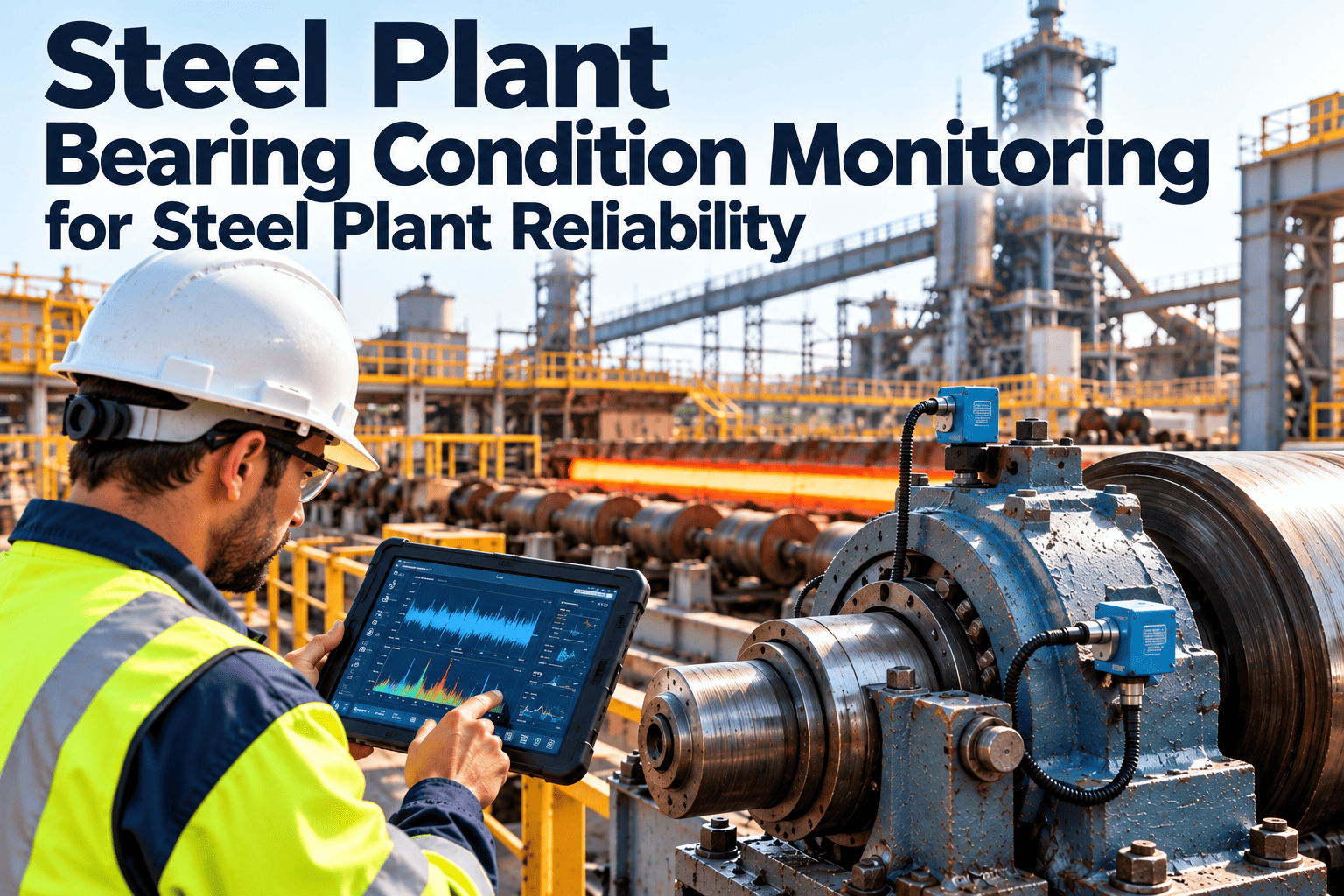
Permanent accelerometers on roller table bearing housings, conveyor head/tail pulleys, transfer car wheel bearings, and cooling bed mechanisms. Industrial-grade sensors rated for 185°F+ continuous operation with stainless steel housings and armored cabling to withstand scale, water, and mechanical damage.
What it detects
Bearing inner race, outer race, rolling element, and cage defects via envelope demodulation. Roller imbalance and eccentricity via 1x vibration. Misalignment via 2x harmonics. Looseness via broadband vibration increase. Gear mesh abnormalities on geared conveyor drives via order tracking.
Detection lead time
3–6 months for bearing defects detected at the subsurface fatigue stage. 1–3 months for roller surface degradation and alignment issues. Real-time alarming for sudden catastrophic events.
Steel-specific consideration: Background vibration from rolling operations, material handling impacts, and adjacent equipment creates high noise floors. Signal processing must use synchronous time averaging and high-pass filtering to extract bearing fault signatures from process noise.
2
Infrared Thermography — The Rapid Screening Layer
All accessible assets
Application in steel
Route-based thermal imaging of conveyor bearing housings, roller table bearings, drive motor connections, and belt conveyor pulleys during production. Fixed thermal cameras on critical roller tables providing continuous temperature trending for each bearing position.
What it detects
Bearing overheating from lubrication failure, excessive friction, or internal damage. Roller surface hot spots indicating internal defects. Conveyor belt tracking problems. Drive motor overheating. Electrical connection hot spots. Comparative analysis between identical bearings reveals the outlier regardless of absolute temperature.
Detection lead time
2–6 weeks for progressive bearing thermal anomalies. Immediate detection for lubrication failures and electrical faults. Thermal trend analysis extends warning to 1–3 months when baseline data is available.
Steel-specific consideration: Radiant heat from hot steel, furnaces, and process equipment creates complex thermal backgrounds. Thermal imaging must account for reflected radiant energy and emissivity variations on oxidized and clean steel surfaces.
3
Ultrasonic Monitoring — The Lubrication Intelligence Layer
Grease-lubricated bearings
Application in steel
Handheld or permanently mounted ultrasonic sensors on conveyor idler bearings, roller table bearing housings, and cooling bed mechanisms. Particularly valuable for grease-lubricated bearings where lubricant condition directly determines bearing life and ultrasonic energy responds immediately to lubrication changes.
What it detects
Under-lubrication (increased friction produces elevated ultrasonic energy), over-lubrication (hydraulic pressure in the bearing housing produces characteristic ultrasonic signature), bearing surface defects at earlier stages than conventional vibration, and seal leakage allowing contaminant ingress.
Detection lead time
Immediate feedback on lubrication condition. 4–8 months advance warning for fatigue-initiated bearing defects — the longest detection lead time of any technology for this failure mode.
Steel-specific consideration: Ultrasonic monitoring guides precision lubrication — grease applied until ultrasonic energy drops to baseline, then stopped. This prevents both under- and over-lubrication, which are the #1 and #2 causes of bearing failure in steel plant conveyors.
4
Oil & Grease Analysis — The Contamination Intelligence Layer
Oil-lubricated & large bearings
Application in steel
Scheduled grease sampling from large roller table bearings and oil sampling from oil-lubricated conveyor gearboxes. Analytical ferrography on samples showing elevated wear metals. Online particle counters on critical gearbox oil systems for real-time contamination monitoring.
What it detects
Water contamination (the #1 lubricant killer in steel plants), iron oxide particle contamination from mill scale, wear metal concentrations indicating specific component degradation (iron from gears and bearings, copper from cages, tin from babbitt), lubricant degradation from thermal and oxidative breakdown.
Detection lead time
2–4 months for progressive wear trending. Immediate contamination detection enabling corrective action before bearing damage occurs. Water contamination identified before it causes hydrogen embrittlement.
Steel-specific consideration: Water content targets for steel plant bearing lubricants should be <200 ppm — far below the 500 ppm threshold used in clean industrial environments — because steel plant bearings already operate at elevated temperatures and loads that reduce their tolerance for lubricant contamination.
Turn Monitoring Data into Maintenance Action
OxMaint connects condition monitoring alerts to your maintenance workflow — when a bearing vibration threshold is exceeded or a thermal anomaly is detected, the system automatically generates a prioritized work order with the right parts, the right instructions, and the right timing to prevent the failure.
Critical Monitoring Zones in the Steel Plant
Not every bearing in a steel plant can or should receive the same monitoring investment. Prioritization by zone ensures that the highest-consequence, hardest-to-access, and fastest-degrading assets receive continuous monitoring while lower-criticality assets are covered by route-based programs.
Why critical: 200–400 roller bearings operating at the highest temperature, water exposure, and impact loading in the mill. A single seized roller stops the entire hot strip mill — $50K–$150K/hour in lost production. Roller table failures are the #1 cause of unplanned hot mill stops at many steel plants.
Monitoring approach: Continuous online vibration on every 3rd–5th roller position (critical coverage), fixed thermal cameras scanning roller bearing temperatures, ultrasonic-guided lubrication on all grease points, monthly route-based vibration on positions between online sensors.
Typical prevention value: $1.5M–$4M annually from avoided unplanned hot mill stops
Why critical: Segment roller bearings operate in direct water spray at temperatures cycling between 200–600°F. Water contamination and thermal cycling are the dominant failure modes. A segment bearing failure during casting can cause a breakout — molten steel escaping containment — with safety, equipment, and production consequences measured in millions.
Monitoring approach: Online vibration monitoring on withdrawal roll bearings, thermal monitoring of segment cooling water outlet temperatures (bearing failure causes localized temperature anomaly), oil analysis on segment hydraulic and lubrication systems, visual inspection of roll surface condition during strand changes.
Typical prevention value: $2M–$6M annually from breakout prevention and reduced unplanned casting stops
Why critical: Belt conveyors moving iron ore, coal, and flux operate 24/7 with thousands of idler bearings exposed to abrasive dust, rain, and temperature extremes. Individual idler failures cause belt damage ($50K–$200K per belt replacement), and head/tail pulley bearing failures stop the entire material feed chain.
Monitoring approach: Online vibration on head and tail pulley bearings, acoustic walk-by screening for idler bearings (failed idlers produce audible noise detectable by handheld or drone-mounted acoustic sensors), thermal imaging of pulley bearings and belt tracking, belt condition monitoring via rip detection and splice monitoring.
Typical prevention value: $800K–$2M annually from belt damage prevention and avoided material supply interruptions
Why critical: Cooling bed mechanisms, walking beam systems, transfer car wheels, and coil handling equipment operate with heavy shock loads and moderate heat exposure. Failures don't stop the mill immediately but create bottlenecks that reduce throughput by 10–25% until repaired.
Monitoring approach: Route-based vibration on a 2–4 week cycle, thermal imaging during production, ultrasonic lubrication monitoring on grease-lubricated bearings, motor current analysis on transfer car drive motors to detect wheel bearing degradation through load signature changes.
Typical prevention value: $400K–$1.2M annually from throughput optimization and planned maintenance scheduling
ROI: Condition Monitoring for Steel Plant Conveyors, Bearings & Rollers
$3.8M
Avoided Unplanned Production Stops
Prevention of 15–25 bearing/roller-related unplanned stops per year × $100K–$200K average cost per event
$1.4M
Extended Component Life
Running bearings and rollers to actual condition-based end-of-life instead of calendar intervals extends useful life 25–45%
$900K
Secondary Damage Prevention
Early bearing intervention prevents cascading damage to rollers, conveyor belts, housings, and adjacent components
$650K
Optimized Outage Planning
Condition data enables batching repairs into planned outages — reducing total shutdown duration 20–35%
$350K
Lubrication Optimization
Ultrasonic-guided precision lubrication reduces grease consumption 30–40% while improving bearing protection
Expert Perspective: Making Condition Monitoring Work in a Steel Plant
"
I've built condition monitoring programs at three integrated steel mills over 18 years. The biggest mistake I see is trying to monitor everything at once. A steel plant has 30,000 bearings — you can't instrument all of them, and you don't need to. Start with the run-out table and the caster withdrawal rolls. Those two zones account for 60–70% of your unplanned bearing-related production losses. Install online vibration on those assets, connect the alerts to your CMMS, and prove the value in the first six months. Once you've documented $2–3 million in prevented failures, funding for the next phase takes care of itself. The second lesson is that vibration monitoring alone isn't enough in a steel plant. Water contamination and lubrication failure kill more bearings than fatigue does — and vibration only detects those failures after the bearing damage has started. Pair vibration with ultrasonic-guided lubrication and you'll prevent 40% of the failures that vibration would have detected. The best bearing failure is the one you prevented with the right grease at the right time, not the one you detected three months before it happened. The third lesson: close the loop. I've seen plants with $500,000 in monitoring equipment where the data lives in a software silo that nobody in maintenance looks at. The vibration analyst generates reports. The maintenance planner doesn't read them. The work order goes unscheduled. The bearing fails on a Saturday night. Connect the monitoring system to the CMMS so that an alert automatically creates a work order with the right priority, the right spare parts, and the right procedure — and route it to the planner's queue without any human in the middle.
Start with the run-out table and caster — they account for 60–70% of bearing-related production losses
Pair vibration with ultrasonic lubrication — prevent 40% of failures before they even start
Close the loop to the CMMS — monitoring data without automatic work orders is just expensive data collection
Account for contamination — water and scale kill more steel plant bearings than fatigue does
Condition monitoring for steel plant conveyors, bearings, and rollers is the highest-leverage reliability investment for the components that keep material moving between every process step. The technology is proven, the ROI is compelling, and the alternative—waiting for catastrophic failure—costs orders of magnitude more. If you're ready to connect condition monitoring to maintenance action, book a free demo to see how monitoring-driven work orders integrate with your maintenance operation.
Monitor. Detect. Plan. Prevent. Keep Steel Moving.
OxMaint connects your condition monitoring systems to maintenance execution — automatically generating work orders when bearing health deteriorates, tracking repair history against specific assets, and building the data foundation that makes predictive analytics smarter with every intervention.
Frequently Asked Questions
How do vibration sensors survive the extreme conditions near hot rolling mills?
Vibration sensors installed near hot rolling operations require industrial-grade construction specifically designed for steel plant environments. Standard industrial accelerometers rated to 185°F (85°C) are adequate for most conveyor and cooling bed applications. For run-out table and caster-area installations where ambient temperatures routinely exceed 200°F, high-temperature accelerometers rated to 300°F+ (150°C+) with stainless steel housings and hermetically sealed connectors are required. Sensor mounting uses welded mounting pads or high-temperature epoxy rather than magnets (which lose holding force above Curie temperature) or adhesives (which fail in heat and moisture). Cabling uses armored, high-temperature cable routed through conduit or cable tray to protect against mechanical damage, radiant heat, and water spray. In the most extreme locations — directly adjacent to the hot strip path — sensors can be mounted on water-cooled brackets that maintain the sensor within its operating temperature range while the surrounding environment exceeds it. Wireless vibration sensors eliminate cabling challenges but must use industrial-grade transmitters with extended battery life rated for the steel plant temperature and electromagnetic environment.
How many sensors are needed for a hot strip mill run-out table monitoring program?
A typical hot strip mill run-out table has 100–200 roller positions between the finishing mill and the coiler. Full instrumentation of every bearing on every roller would require 200–400 vibration sensors (one per bearing, two per roller) — a significant investment of $600K–$1.2M in sensors, cabling, and data acquisition alone. The proven, cost-effective approach uses a tiered strategy. Continuous online monitoring on every 3rd to 5th roller position (40–70 sensors) provides detection coverage for 85–90% of the table, because bearing degradation is typically detectable on adjacent monitored positions before it reaches catastrophic failure. Fixed infrared thermal cameras scanning the entire table provide 100% coverage for thermal anomalies at a fraction of the per-point cost of vibration sensors. Monthly route-based portable vibration collection fills gaps between online sensor positions. This tiered approach typically costs $200K–$400K for sensors and infrastructure — 30–50% of the full instrumentation cost — while achieving nearly equivalent detection capability. As sensor and wireless technology costs continue to decrease, expanding coverage toward every-roller monitoring becomes increasingly practical.
Can condition monitoring detect conveyor belt problems in addition to bearing failures?
Yes — modern condition monitoring programs for steel plant conveyors extend well beyond bearing health to cover the belt itself and related structural components. Belt condition monitoring technologies include longitudinal rip detection systems that use embedded loop sensors or cord monitoring to detect rips in real time before they propagate the full belt length (a full-length rip destroys a $50K–$200K belt in seconds). Splice monitoring uses electromagnetic or X-ray inspection to assess splice integrity during operation — splice failures are the most common cause of belt breaks. Belt tracking sensors detect misalignment before the belt contacts the conveyor structure and causes edge damage. Belt thickness measurement using electromagnetic or ultrasonic gauges tracks wear progression and predicts remaining belt life. Additionally, pulley lagging condition is assessed through thermal imaging (worn lagging causes belt slip, generating heat), and belt tension is monitored through deflection measurement or load cell systems. The combination of bearing monitoring, belt condition monitoring, and structural monitoring provides comprehensive health assessment of the entire conveyor system — not just the rotating components.
What is ultrasonic-guided lubrication and how does it prevent bearing failures?
Ultrasonic-guided lubrication uses an ultrasonic sensor to listen to the bearing during grease application and determine the optimal amount to apply — solving the two most common lubrication failures: under-lubrication and over-lubrication. A bearing that needs grease produces elevated ultrasonic energy because metal-to-metal contact between rolling elements and races generates high-frequency stress waves. As grease is applied, the ultrasonic energy level drops as the lubricant film re-establishes between contact surfaces. The technician or automatic lubrication system applies grease until the ultrasonic level drops to the established baseline — then stops. This prevents under-lubrication (the #1 cause of premature bearing failure in steel plants, responsible for approximately 40% of bearing failures) by ensuring adequate lubricant film. It equally prevents over-lubrication (the #2 cause, responsible for approximately 25% of failures) by stopping grease application when the bearing is properly lubricated. Over-lubrication is particularly damaging because excess grease generates internal heat, increases hydraulic pressure on seals, and can push contaminants past seals into the bearing. The combined effect of eliminating both under- and over-lubrication typically extends bearing life by 30–50% in steel plant applications while reducing total grease consumption by 30–40%.
How do we prioritize which bearings to monitor when we have tens of thousands?
Prioritization uses a risk-based framework that considers three dimensions: consequence of failure, probability of failure, and current detectability. Score each dimension on a 1–5 scale and multiply to get a composite risk score. Consequence of failure: What happens when this bearing fails? A run-out table roller bearing that stops the hot strip mill (score: 5) versus a warehouse conveyor idler that causes a minor delay (score: 1). Factors include production loss rate, safety implications, secondary damage potential, and repair time. Probability of failure: How likely is this bearing to fail? Consider equipment age, operating environment severity, historical failure frequency, and maintenance condition. Run-out table bearings in the water spray zone (score: 5) versus warehouse bearings in a clean, dry environment (score: 1). Current detectability: Can you currently detect a developing failure before it becomes catastrophic? A bearing with no monitoring on an inaccessible roller (score: 5, meaning low detectability is bad) versus a bearing with online vibration monitoring (score: 1). The composite risk score naturally directs monitoring investment to the assets where it has the highest impact. Typically, 5–10% of bearings account for 60–80% of the total risk — and these are where monitoring investment should start.