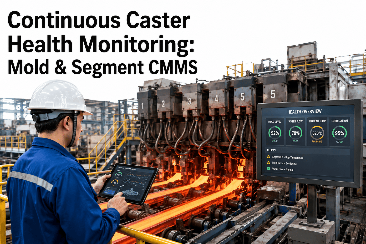
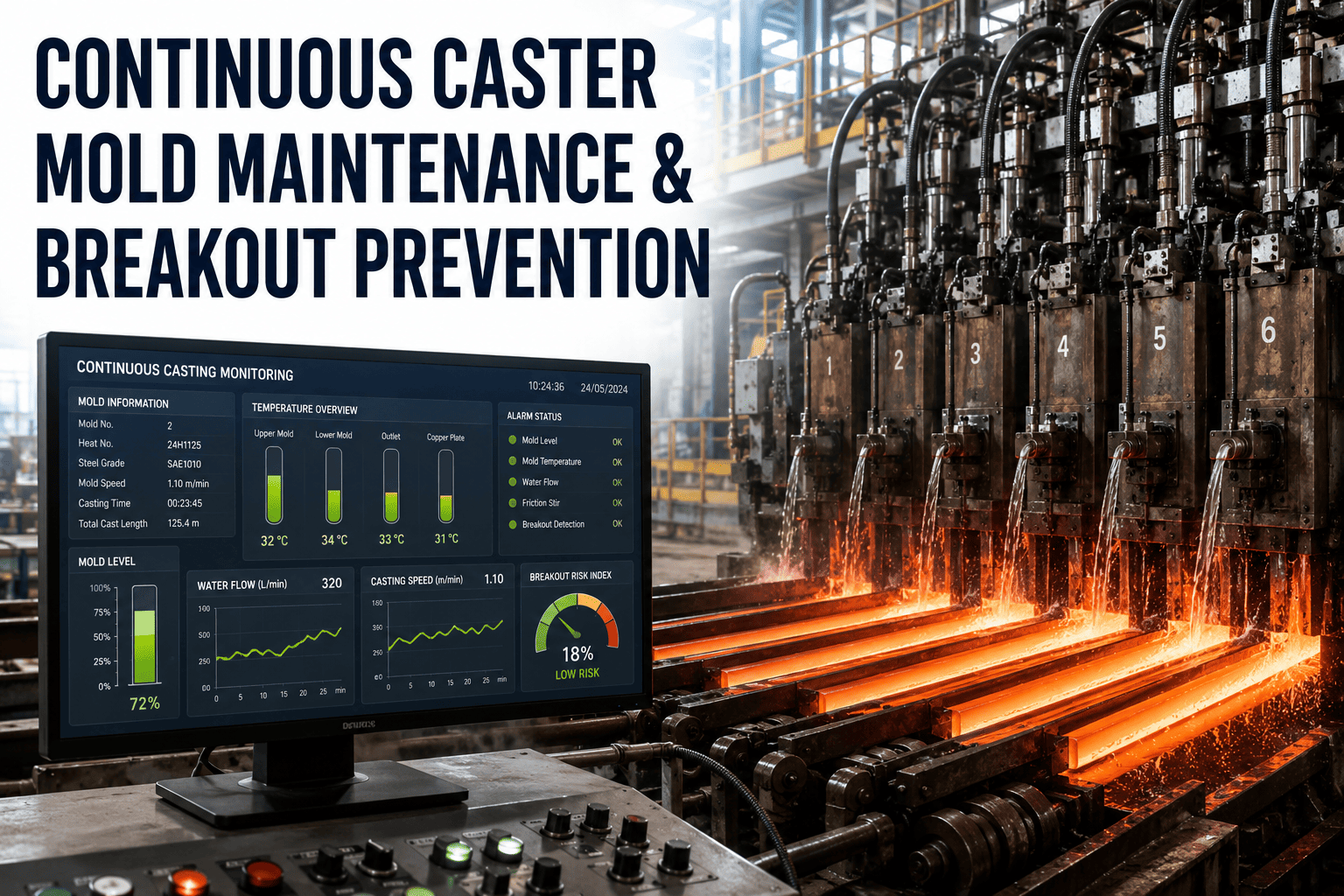
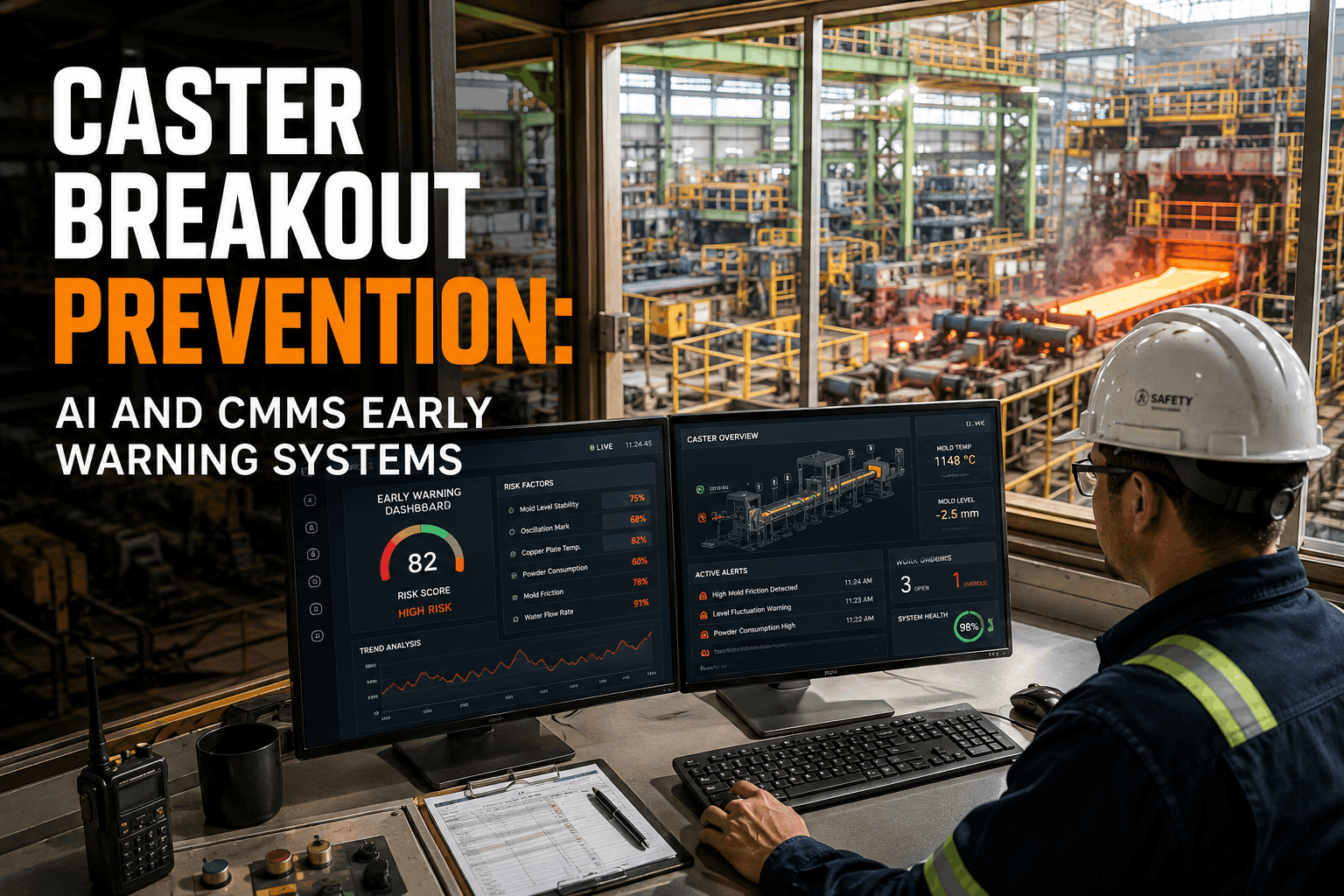
A breakout is the most dangerous and expensive event in continuous casting. Molten steel at 1,550°C ruptures through the partially solidified shell inside the mold or in the strand containment section, releasing liquid metal into the machine — destroying segment rolls, spray nozzles, bearings, and guide equipment in seconds. A single breakout event costs $500K–$3M in direct equipment damage, 8–48 hours of lost production worth $800K–$10M depending on the caster configuration, and creates a safety hazard that can injure or kill operators working near the machine. Integrated mills running two-strand slab casters at 1.5–3M tons per year experience 5–25 breakout events annually, with total annual breakout costs of $5M–$30M when direct damage, production loss, and quality impact on surrounding heats are combined. Every breakout is preventable. The solidifying shell that contains the liquid steel is formed and supported by equipment that can be monitored, maintained, and controlled: the mold copper plates that extract heat to form the initial shell, the mold oscillation system that prevents the shell from sticking, the mold flux that lubricates the interface between shell and copper, the secondary cooling sprays that continue solidification below the mold, and the containment rolls that support the shell against ferrostatic pressure until it's strong enough to stand alone. When any of these systems degrades — mold copper worn past tolerance, oscillation stroke drifting, spray nozzle blocked, segment roll seized, alignment shifted — the shell thins locally, and if the thinning exceeds the shell's ability to contain the liquid core, it ruptures. The time between "equipment degradation detectable" and "breakout occurs" can be weeks, days, or hours depending on the failure mode. A CMMS that tracks every mold, every segment, every spray zone, every roll, and every sensor creates the maintenance framework that keeps every component within the tolerances that prevent shell thinning — and ultimately prevent breakouts.
Breakout: The Most Expensive Word in Steelmaking
$500K–$3M
Direct equipment damage per breakout event
8–48 hours
Lost production per event — caster offline for cleanup and repair
5–25/year
Breakout frequency at typical integrated mill casters
$5M–$30M
Total annual breakout cost (damage + production loss + quality)
100%
Preventable — every breakout traces to a detectable equipment or process condition
How Breakouts Happen: The Equipment Failures That Thin the Shell
A breakout doesn't happen because something catastrophically fails in an instant. It happens because an equipment condition degrades over days or weeks, progressively thinning the solidifying shell until the remaining shell can no longer contain the ferrostatic pressure of the liquid steel above it. Understanding the specific equipment failure → shell thinning → breakout pathway is the foundation of prevention. Plants that track caster equipment condition on a centralized maintenance platform can detect degradation before it reaches the shell-thinning threshold.
01
Mold Copper Plate Wear
Cause of 25–35% of breakouts
Degradation
Copper plate thickness decreases from wear and erosion — losing 0.3–1.0mm per campaign of 500–2,000 heats. Nickel/chrome coating wears through locally, exposing bare copper to direct steel contact. Worn areas develop uneven heat extraction.
→
Shell thinning
Uneven heat extraction creates thin spots in the solidifying shell. Where the copper is worn thin, the shell grows faster initially (higher heat flux) but the disturbed solidification front creates a weak, irregular shell with reduced hot strength.
→
Breakout
Thin shell section tears under ferrostatic pressure as it exits the mold. Liquid steel pours through the rupture into the segment section below.
CMMS prevention: Mold copper plate thickness measured after every campaign. Coating thickness tracked by zone. Plates replaced or recoated when minimum thickness is reached at any point — not average thickness.
02
Mold Oscillation System Failure
Cause of 15–20% of breakouts
Degradation
Hydraulic oscillation cylinders lose precision — stroke deviation exceeds ±0.2mm, non-sinusoidal motion develops from worn seals or degraded servo valves. Oscillation frequency drifts from optimal casting speed ratio.
→
Shell thinning
Improper oscillation creates "sticker" conditions — the solidifying shell momentarily bonds to the mold copper. When the strand continues withdrawing, the bonded section tears, creating a thin spot or hole in the shell.
→
Breakout
Sticker breakout — the torn shell section exits the mold with a hole or critically thin area that ruptures under ferrostatic pressure. Sticker breakouts are the most common breakout type.
CMMS prevention: Oscillation stroke and frequency monitored continuously. Servo valve response time tested monthly. Hydraulic cylinder seal replacement on condition. Oscillation guide bearing clearance measured quarterly.
03
Secondary Cooling Spray Degradation
Cause of 15–25% of breakouts
Degradation
Spray nozzles plug from scale buildup, water quality minerals, or debris. Individual nozzles lose 30–100% of flow capacity. Water supply headers develop pressure drops from internal corrosion. Nozzle spray patterns distort from erosion.
→
Shell thinning
Plugged or degraded nozzles create zones of reduced cooling below the mold. The shell, which exited the mold at 10–20mm thickness, doesn't continue solidifying at the expected rate. Ferrostatic pressure from the liquid core bulges the thin shell outward between containment rolls.
→
Breakout
Bulging shell contacts a segment roll and tears, or the shell simply ruptures from exceeding its hot strength at the reduced thickness. Below-mold breakouts damage containment segments — the most expensive equipment to repair.
CMMS prevention: Spray nozzle inspection every strand change or outage. Nozzle flow testing quarterly. Water quality monitoring (conductivity, hardness, pH) continuous. Spray zone flow rate trending per zone versus setpoint.
04
Segment Roll & Alignment Failure
Cause of 10–20% of breakouts
Degradation
Segment rolls seize from bearing failure (water ingress, heat, fatigue), creating flat spots. Segment alignment drifts from foundation settlement or bolt loosening. Roll gap deviates from target — either too wide (insufficient shell support) or too narrow (excessive mechanical stress on shell).
→
Shell thinning
Seized rolls create localized hot spots from friction. Misaligned segments allow excessive bulging between roll pairs, straining the shell. Incorrect roll gap creates either unsupported shell spans or mechanical damage to the shell surface.
→
Breakout
Shell ruptures at the point of maximum bulging or at the seized roll contact point. Segment breakouts cause the most extensive equipment damage because liquid steel floods the entire segment section.
CMMS prevention: Segment roll rotation check every outage (manual turn test or rotation sensor). Bearing vibration/temperature monitoring on critical segments. Segment alignment laser measurement quarterly. Roll gap verification during every segment change.
05
Mold Level Control & SEN Condition
Cause of 10–15% of breakouts
Degradation
Submerged Entry Nozzle (SEN) erodes asymmetrically, creating biased flow that pushes the liquid steel stream toward one mold wall. Mold level sensor drifts from calibration. Slide gate or stopper rod actuator response slows from hydraulic wear.
→
Shell thinning
Biased flow from eroded SEN washes one side of the solidifying shell with turbulent liquid steel, remelting and thinning it. Mold level fluctuations (±10mm+) create alternating exposed/submerged conditions at the meniscus that produce weak shell with slag entrapment.
→
Breakout
Thinned shell on the biased-flow side ruptures. Or slag-weakened shell at the meniscus creates a sticker-type breakout. Mold level upsets can also cause overflow — liquid steel spilling over the mold top.
CMMS prevention: SEN life tracking by heat count with maximum life limits. Mold level sensor calibration weekly. Slide gate/stopper rod actuator response time testing monthly. Flow control hydraulic system PM per schedule.
Every Breakout Has a Maintenance Root Cause. Every Root Cause Is Detectable. Every Detection Requires Tracking.
OxMaint tracks every mold plate, every oscillation system, every spray nozzle, every segment roll, and every sensor on your caster — creating the equipment condition visibility that prevents breakouts before they happen.
Mold Thermocouple Breakout Detection: The Last Line of Defense
Mold thermocouple breakout detection systems (BDS) are the real-time safety net that catches sticker-type breakouts in progress — detecting the characteristic thermal pattern of a shell tear as it propagates up the mold, and automatically reducing casting speed or stopping the strand before the tear exits the mold. But this safety net only works when the thermocouples are working.
A breakout detection system with failed thermocouples is like a smoke detector with dead batteries — it provides false confidence. Typical slab caster molds contain 100–200+ thermocouples arranged in 4–8 rows across the mold width. When thermocouples fail, blind spots appear in the detection grid. If a sticker develops in a blind spot, the BDS cannot detect the characteristic pattern and the breakout proceeds uncaught. Industry data shows that molds with more than 10–15% thermocouple failure rate have breakout detection reliability below 80% — meaning 1 in 5 sticker events will not trigger automatic protection.
Track per mold: Total thermocouples installed, number functional, failure rate, and spatial distribution of failures (clustered failures are more dangerous than distributed ones)
Replace threshold: Automatic work order for thermocouple replacement when functional count drops below 90% or when any mold face has two adjacent failed thermocouples in the same row
Calibration: Thermocouple accuracy verification during every mold change — compare readings against reference thermocouples at known temperature
BDS system testing: Monthly simulated sticker injection test to verify the detection algorithm, alarm response, and automatic speed reduction function end-to-end
Segment Maintenance: The Containment System Below the Mold
Below the mold, 8–20 containment segments (each weighing 20–60 tons) support the strand through the bending, straightening, and horizontal sections. Each segment contains 6–12 pairs of rolls, water spray nozzles, hydraulic clamping cylinders, and instrumentation — totaling 1,000+ individual components per caster strand that must be maintained within tolerance to prevent shell damage and breakouts.
Zone 1 — Foot Rolls & Bender
HIGHEST CRITICALITY — Thinnest shell, maximum breakout risk
Immediately below the mold where the shell is only 10–25mm thick. The shell must transition from vertical to the bending radius while under full ferrostatic pressure. Roll spacing is tightest here (150–250mm pitch). A single seized roll or misaligned segment in this zone creates the highest breakout probability.
Roll rotation check: every outageBearing inspection: monthlyAlignment: every segment changeSpray nozzle check: every outage
Zone 2 — Curved Section
HIGH CRITICALITY — Shell under bending stress + ferrostatic pressure
Segments guiding the strand through the constant radius section. Shell thickness grows to 30–60mm through this zone. The combination of bending stress and ferrostatic pressure makes this zone sensitive to roll gap accuracy — incorrect gap allows bulging that strains the shell and can cause internal cracking or breakout in severe cases.
Roll rotation check: every outageRoll gap measurement: quarterlyHydraulic clamping pressure: monthlySpray coverage: every outage
Zone 3 — Straightener
HIGH CRITICALITY — Unbending stress on partially solidified strand
The strand transitions from curved to horizontal. Unbending creates tensile stress on the inner radius surface of the shell — the most common location for transverse (straightening) cracks. Segment alignment and roll condition are critical: misalignment introduces asymmetric bending that concentrates stress and creates crack initiation sites.
Roll surface inspection: quarterlyAlignment laser survey: quarterlyBearing vibration: route-based monthlyGap + taper verification: every change
Shell thickness reaches 80–150mm+. Breakout risk is low but not zero — a severely misaligned segment can still damage the shell. The primary maintenance focus shifts to quality: roll condition affects surface quality, spray uniformity affects internal soundness, and segment alignment affects strand geometry that determines cutting accuracy and downstream rolling behavior.
Roll rotation check: monthlyAlignment survey: semi-annualSpray maintenance: quarterlyHydraulic system PM: monthly
Mold Maintenance: The First 800mm That Determine Everything
The mold is an 800–1,000mm long water-cooled copper chamber where the steel first contacts a solid surface and begins solidifying. Everything that happens in the mold — heat extraction rate, oscillation behavior, mold flux performance, meniscus stability — determines the quality and integrity of the shell that must survive the entire 10–30 meter journey through the machine. Book a demo to see how OxMaint tracks mold lifecycle and maintenance.
Copper Plate Lifecycle
3–8 campaigns / 1,500–10,000 heats
Track thickness at 20–40 measurement points per plate after every campaign. Wear rate varies by position: meniscus area wears fastest (direct thermal cycling + flux erosion), narrow face centers wear from strand drag, and bolt hole regions develop stress cracking. Plates are reconditioned (machined + recoated) between campaigns until minimum thickness is reached, then retired.
CMMS tracks: Heats per campaign, thickness measurements per point per campaign, coating condition, reconditioning history, total heats lifetime, minimum thickness approach
Mold Cooling Water
Continuous monitoring required
Mold cooling water flow rate and temperature differential across the mold are the primary indicators of heat extraction performance. Reduced flow from scaling, debris, or pump degradation directly reduces shell thickness at mold exit. A 10% flow reduction can thin the exit shell enough to increase breakout risk measurably. Water quality (conductivity, hardness, pH) determines scaling rate in the narrow cooling channels.
CMMS tracks: Water flow rate per mold face trending, delta-T trending, water quality test results, cooling channel cleaning schedule, pump PM and performance verification
Oscillation System
Continuous operation, PM every campaign change
Hydraulic oscillators must maintain stroke accuracy within ±0.1mm and waveform fidelity (non-sinusoidal deviation <5%) across the full speed range. Guide bearings, leaf springs, or hydraulic bearings wear progressively — introducing play that manifests as stroke deviation and potential sticker risk. Oscillation monitoring systems track actual stroke, frequency, and waveform in real time.
CMMS tracks: Stroke measurement trends, waveform deviation records, guide bearing clearance measurements, hydraulic servo valve response time tests, spring inspection records
Mold Width Adjustment
PM quarterly, full overhaul annually
Narrow face positioning mechanisms (hydraulic or electromechanical) set and adjust slab width during casting. Position accuracy requirements: ±0.5mm. Wear in the drive mechanism, guide rails, or clamping system creates width variation, taper deviation, and narrow face instability that leads to longitudinal corner cracks and increased breakout risk at width change transitions.
Annual ROI — 2-Strand Slab Caster (1.5–3M tons/year)
$8.5M
Breakout Prevention & Reduction
60–80% reduction in breakout events through maintenance-driven prevention — from 15–25 events/year to 3–8 — each avoided event worth $1M–$5M in combined damage and production loss
$3.2M
Mold & Segment Component Life Optimization
15–30% extended mold plate life, 20–40% extended segment roll bearing life through condition-based replacement rather than conservative calendar intervals
$2.1M
Caster Availability Improvement
2–4% caster availability increase through planned maintenance replacing unplanned stops — each 1% availability on a 2M ton caster = 20,000 tons additional production
I managed caster maintenance at three different plants over 22 years. At the first plant, we accepted breakouts as inevitable — "it's casting, breakouts happen" was the culture. We averaged 20 breakouts per year across two strands and spent $12M annually on breakout damage and lost production. At the second plant, we installed a breakout detection system and thought the problem was solved. Breakout detection caught about 70% of sticker events, which was a significant improvement, but we still had 8–12 breakouts per year from BDS misses, below-mold breakouts the BDS can't detect, and sticker events that developed too fast for the speed reduction to prevent shell rupture. At the third plant, we changed the approach entirely. Instead of detecting breakouts in progress and hoping to stop them, we prevented the conditions that cause breakouts from developing in the first place. We implemented comprehensive CMMS tracking of every mold plate thickness at 36 measurement points per campaign, every oscillation parameter continuously, every thermocouple status daily, every spray nozzle flow quarterly, every segment roll rotation and alignment per change, and every water quality parameter continuously. In the first year, breakouts dropped from 14 to 6. By year three, we achieved 2 breakouts — both from operational upsets, not maintenance failures. The maintenance cost per ton actually decreased because we stopped spending $8M per year on breakout repairs and redirected a fraction of that into the preventive program. The single most important insight: breakout prevention is not about technology — it's about discipline. Every thermocouple working. Every spray nozzle flowing. Every roll turning. Every measurement within tolerance. Every time. The CMMS doesn't prevent breakouts by itself. It prevents the human failures — forgotten inspections, lost records, deferred maintenance, missed trends — that allow equipment to degrade to the point where a breakout becomes possible.
Prevention beats detection — stopping breakout conditions from developing is more effective than catching breakouts in progress
Track every thermocouple — a BDS with 15% failed sensors misses 1 in 5 sticker events
Measure mold copper at 20–40 points per plate — minimum thickness at any point, not average, drives the replacement decision
Discipline over technology — every thermocouple working, every nozzle flowing, every roll turning, every measurement within tolerance, every time
Continuous casting machine maintenance is fundamentally breakout prevention — maintaining the equipment systems that create, support, and cool the solidifying shell to tolerances that ensure the shell never thins to the point of rupture. Every breakout traces back to a maintenance failure that was detectable weeks or months before the event. If you're ready to build the maintenance tracking system that drives toward zero breakouts, book a free demo to see how caster maintenance management works on OxMaint.
Every Mold Tracked. Every Segment Aligned. Every Nozzle Flowing. Every Breakout Prevented.
OxMaint delivers complete caster maintenance management — mold plate lifecycle tracking, oscillation system monitoring, thermocouple health management, spray nozzle inspection scheduling, segment roll condition tracking, alignment records, and breakout event investigation with root cause to corrective action traceability.
How does a mold thermocouple breakout detection system (BDS) work?
A BDS uses an array of 100–200+ thermocouples embedded in the copper mold plates, arranged in 4–8 horizontal rows at different heights in the mold. During normal casting, each thermocouple reads a stable temperature (typically 150–200°C) that reflects the heat flow from the liquid steel through the solidified shell and copper plate to the cooling water. When a sticker occurs — the shell tears and liquid steel contacts the copper directly — the thermocouple nearest the sticker location sees a sudden temperature spike (50–150°C above normal) because molten steel at 1,550°C is now in direct contact with the copper instead of being separated by a 10–20mm solidified shell. The BDS algorithm looks for the characteristic sticker "signature": a temperature spike that propagates sequentially from lower to upper thermocouple rows as the tear travels up the mold wall with the strand movement.
How often should caster segments be changed and what determines the interval?
Segment change intervals vary significantly by zone position and operating conditions, typically ranging from 2,000 to 8,000 heats. The primary factors determining change interval are: roll bearing life (the most common life-limiting component — bearings in the upper segments near the mold face shorter life due to higher temperatures and water spray exposure), roll surface condition (surface cracking, buildup, and wear create strand surface defects), spray nozzle degradation (progressive plugging reduces cooling effectiveness), and alignment stability (segment frame distortion from thermal cycling gradually shifts roll positions out of tolerance).
What is the relationship between breakout detection and breakout prevention?
Breakout detection and breakout prevention are complementary but fundamentally different strategies, and the most effective caster maintenance programs rely primarily on prevention with detection as the safety backup. Breakout detection (BDS) catches breakouts in progress — it identifies a sticker or shell tear after it has already occurred and attempts to stop the tear from becoming a full breakout by reducing casting speed. Detection has inherent limitations: it can only catch sticker-type breakouts in the mold (not below-mold breakouts from spray or segment failures), it requires functional thermocouples in the right locations (blind spots from failed thermocouples reduce detection probability), and it must react within 2–5 seconds (some fast-developing stickers propagate faster than the response cycle).
How does water quality affect caster maintenance and breakout risk?
Water quality affects both mold cooling and secondary cooling, with distinct failure mechanisms for each. In the mold, cooling water flows through narrow channels (typically 4–8mm wide) machined into the copper plate back surface. Hard water deposits calcium and magnesium scale on channel walls, progressively restricting flow and reducing heat transfer. A 20% reduction in mold cooling water flow can reduce shell thickness at mold exit by 15–25% — directly increasing breakout risk. Scale buildup is progressive and invisible without flow monitoring. The CMMS tracks mold water flow rate trending per face, delta-T (temperature rise across the mold) trending, and water quality parameters (conductivity as a scaling indicator, pH, hardness, total dissolved solids).
What should a breakout investigation process look like and how does the CMMS support it?
Every breakout should trigger a structured investigation that identifies the root cause and implements corrective action to prevent recurrence. The investigation process, supported by the CMMS, follows a defined sequence. Immediate response (0–4 hours): the breakout event is logged in the CMMS with timestamp, strand, location (mold or segment zone), estimated severity, and initial operator observations. The system automatically pulls the maintenance state snapshot — every active work order, every overdue PM, every recent inspection finding, and the current condition status of every component in the affected zone. Data collection (4–24 hours): BDS thermocouple data from the event is archived, oscillation data from the casting leading up to the breakout is retrieved, mold cooling water flow and temperature data is captured, and the physical breakout shell sample is collected for metallurgical examination.