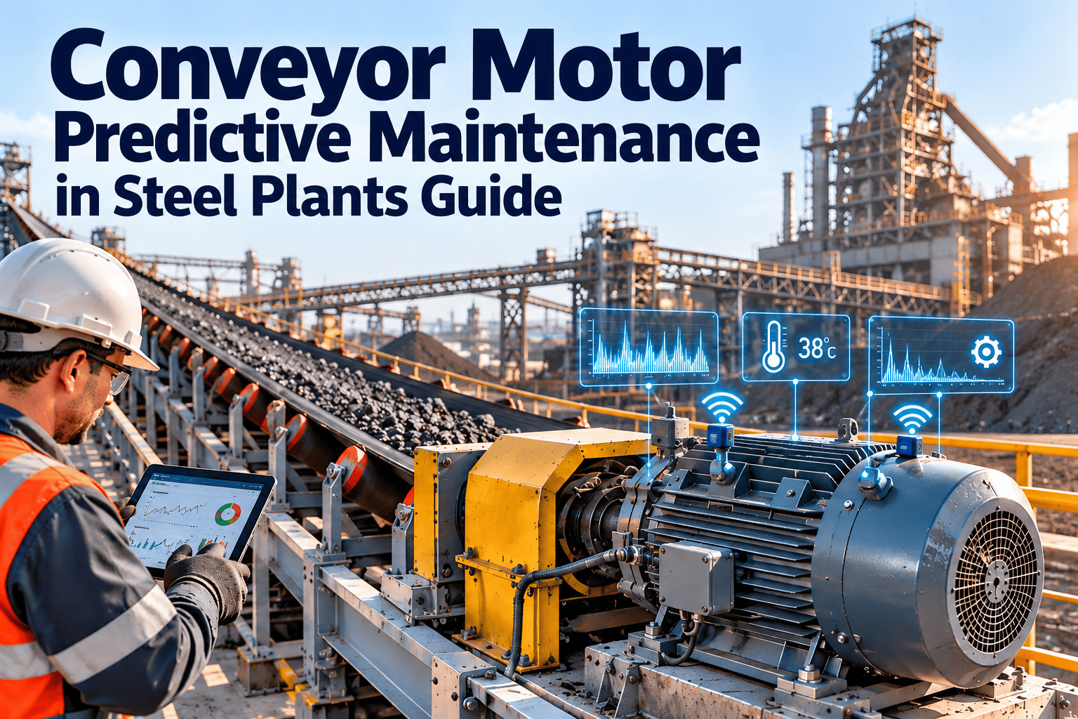
A conveyor motor in a steel plant rarely fails without warning. Overload, bearing wear, misalignment, loose connections and winding stress all change the motor's current draw, temperature and vibration well before the belt stops. The difficulty is that these changes are small, and most plants still find them only after a trip, a burnt winding or a blocked transfer chute. This guide explains how to read those signals, build alarm limits that fit steel mill duty, and turn each finding into a planned job using Oxmaint maintenance software.
Conveyor motor predictive maintenance in steel plants
Ore, coke, sinter and scrap conveyors feed every downstream process. Track current, temperature and vibration on the drive, catch the fault while it is still a planned job, and keep raw material moving.
Why conveyor motors are a weak point in steel plant material handling
Conveyors look simple, yet they connect stockyards, sinter plants, blast furnace stockhouses and scrap yards. When one drive stops, everything behind it stops too.
Dust and heat
Fines, coke dust and sinter dust coat motor frames and block cooling fins. A motor that runs hotter than its design limit ages its insulation faster, even if it never trips.
Heavy starts and shock loads
Loaded belts, chute blockages and surge feeding push starting current and running torque above normal. Repeated stress builds up in rotors, couplings and gearboxes.
Long, remote and hard-to-inspect routes
Drives sit in galleries, tunnels and on tall structures. Manual rounds are infrequent, so slow faults run unnoticed between visits.
Fixed-interval maintenance
Calendar PMs treat a lightly loaded motor and a heavily loaded one the same. One gets over-maintained, the other fails between inspections.
Root causes behind repeat conveyor motor failures
Replacing a burnt motor without asking why it burnt is the most common reason the same drive fails again. These causes appear repeatedly in steel plant material handling.
Mechanical drag upstream of the motor
Seized idlers, worn pulley bearings, misaligned belts and heavy spillage all raise the torque the motor must deliver. The motor pays for a problem that started elsewhere on the route.
Poor lubrication practice
Mixed greases, over-greasing that pushes seals out, and missed intervals shorten bearing life. Without a record on the asset, nobody can confirm what was applied last.
Restricted cooling
Dust packed into fan covers and fins lifts running temperature slowly. The rise is easy to miss without a trend.
Installation and repair quality
Soft foot, rough alignment, wrong bearing fits and reused worn couplings often cause early failure after a repair. A repair checklist with recorded alignment values removes much of this risk.
Electrical supply and connections
Voltage unbalance, loose lugs and degraded cable terminations create heat and current imbalance that damage windings over time.
Operational impact of an unplanned conveyor motor failure
The cost of a failed motor is rarely the motor. The larger cost is what the stopped belt does to the plant.
- Furnace and sinter feed can be interrupted, forcing operators to change charging or blend plans.
- Material spills at transfer points create cleanup work and safety exposure for the crew.
- A stopped loaded belt often needs partial unloading before restart, which adds time and stress to the drive.
- Emergency repairs draw people away from planned work, so the backlog grows.
- Downstream stockyard and bunker levels fall, so operators may need to reschedule deliveries or change stacking and reclaiming plans.
- Maintenance history is often incomplete after an emergency, which weakens the data needed for later root cause analysis and spares planning.
- Rushed repairs increase the chance of a repeat failure, because alignment and inspection steps get shortened.
Condition-based planning turns much of this from an emergency into a scheduled job with tools, spares and permits ready.
What each signal tells you about a conveyor motor
No single measurement covers every failure mode. The table below shows how current, temperature and vibration complement one another on a typical belt drive.
| Failure mode | Current signal | Temperature signal | Vibration signal |
|---|---|---|---|
| Belt or process overload | Sustained rise above the normal loaded current band | Gradual winding temperature rise | Little change until gearbox stress appears |
| Bearing wear | Mostly unchanged early on | Bearing housing rises above sister drives | Bearing defect frequencies and high-frequency energy grow |
| Shaft or coupling misalignment | Slight current increase from added friction | Coupling and bearing heat | Elevated 1x and 2x running speed components |
| Broken or cracked rotor bar | Sidebands around line frequency, current oscillation under load | Localised rotor heating | Pole-pass frequency sidebands |
| Winding or insulation degradation | Current imbalance between phases | Hot spots, rising winding temperature | Twice-line-frequency vibration |
| Loose connection or supply issue | Voltage and current unbalance | Terminal box heat | Usually none until damage develops |
From raw signal to repair: the monitoring chain
Data only prevents downtime if it ends in a job someone completes. A workable chain has five links, and every link needs an owner.
Register the drive
Record motor rating, speed, bearing types, gearbox ratio, belt length and criticality in the asset register.
Capture the baseline
Measure current, temperature and vibration under normal loaded running, not while idle or in a start-up transient.
Set alarm levels
Use warning and action limits relative to the baseline, and compare with sister drives on the same duty.
Trigger the work order
An out-of-limit reading creates a corrective or inspection job with the reading attached.
Close the loop
Record the finding, the part replaced and the new reading, so the next alarm limit is better than the last.
Motor current signature analysis on conveyor drives
Motor current signature analysis, often shortened to MCSA, reads faults from the supply current instead of from a sensor on the machine. It is well suited to conveyors because the drive is often hard to reach.
What the current waveform can reveal
- Rotor bar problems appear as sidebands close to the line frequency in the current spectrum.
- Stator winding faults show up as phase current imbalance and changes in harmonic content.
- Mechanical load problems, such as a jammed idler set or a dragging belt, show as a sustained shift in average current.
- Eccentricity and some gearbox faults leave patterns that repeat at running speed or gear mesh related frequencies.
- Supply quality issues, including voltage unbalance, change current on all phases together.
Practical limits to respect
- Load must be steady enough during the test. A lightly loaded belt hides rotor faults because the sidebands shrink.
- Variable frequency drives change the spectrum, so tests should follow the drive manufacturer's guidance and use a consistent operating point.
- Current analysis works best as a trend. A single reading is much less useful than the change over months.
Thermal monitoring: catching heat before insulation pays for it
Heat is the main enemy of motor insulation, and steel plant conveyors add dust, radiant heat and poor airflow. Thermal trending is inexpensive and effective.
Measure these points
- Motor frame and drive-end bearing housing
- Non-drive-end bearing housing
- Winding temperature sensors where fitted
- Gearbox housing and oil sump
- Coupling guard and terminal box
Read them correctly
- Compare against the same motor's own baseline at similar load and ambient temperature.
- Compare drive-end with non-drive-end. A large gap often points to one failing bearing.
- Compare with a sister drive on the same route.
- Check cooling fins and fan covers whenever a temperature rise appears, because blocked airflow is a common and cheap fix.
Vibration analysis for bearings, alignment and looseness
Vibration remains the most direct way to see mechanical wear. For motors above about 15 kW, ISO 20816-3 gives guidance on evaluating vibration severity on industrial machines.
Typical patterns on a conveyor drive
Lubrication belongs in the same review
Many bearing failures start with too little, too much or the wrong grease. Tie greasing tasks to the same asset as the vibration route, so a reading and a lubrication record can be read together.
Prioritising alarms: a simple risk matrix
Not every alarm deserves the same response. Combine drive criticality with condition severity to decide how fast to act.
Put conveyor motor readings into a maintenance workflow
Start with one critical conveyor route. Register the drives, set baseline limits and let Oxmaint create the work orders when readings move.
Reactive versus predictive conveyor motor maintenance
The change is less about buying sensors and more about how the team responds to information.
Before: run to failure with fixed PMs
- Motor trips during a shift and the belt stops
- Spares searched for after the failure
- Repair timing decided by the breakdown
- Findings kept on paper or in memory
- Same PM interval regardless of load
After: condition-based with linked records
- Trend alarm raises a planned work order
- Spares reserved from inventory before shutdown
- Repair fits a planned outage window
- Readings, photos and parts recorded on the asset
- Inspection frequency follows condition and criticality
Conveyor drive inspection checklist
Predictive data does not replace basic inspection. Use this list to cover what sensors cannot see.
Motor and electrical
- Ventilation openings and fan cover free of dust
- Terminal box sealed, connections tight, no discolouration
- Cable glands and earthing intact
- Starter and drive alarms reviewed
- Phase current balance recorded
Mechanical
- Coupling condition and guard fixing
- Base bolts, soft foot and grout
- Gearbox oil level, colour and leaks
- Brake or holdback condition
- Pulley lagging and belt tracking
Process
- Chute build-up and blockage history
- Skirt board drag and belt cleaner pressure
- Idler seizure along the route
- Feed rate against rated belt capacity
- Spillage around the drive area
Setting baselines and alarm limits that people trust
False alarms destroy confidence quickly. Build limits in stages so the team sees value early.
Select pilot drives
Choose the conveyors that stop the most production or have the worst failure history.
Collect baselines
Take readings under normal load across several shifts and note ambient conditions and material types.
Tune warning and action limits
Review each alarm with the technician who visited the drive. Adjust limits where the machine was healthy.
Extend to more routes
Reuse templates for similar drives and refine criticality rankings using actual outcomes.
Measures that show whether the programme works
Choose a small set of indicators and review them monthly with maintenance and operations together.
How Oxmaint supports conveyor motor maintenance
Oxmaint is maintenance management software that keeps asset records, inspections and jobs in one place. For conveyor motors, these features matter most.
Asset hierarchy
Structure each route from motor to gearbox, coupling, pulley and idler set, with ratings and criticality.
Preventive and condition-based scheduling
Combine calendar tasks such as greasing with reading-based triggers for higher-risk drives.
Mobile inspections
Technicians log temperatures, vibration readings, photos and notes on their phones during rounds.
Work orders and spares
Corrective jobs link to spare motors, bearings and couplings held in inventory.
Reports and dashboards
Track failure history, repeat faults, backlog and PM compliance by conveyor route.
Frequently asked questions
Which signal should we start with on conveyor motors?
Start with temperature and vibration on critical drives, then add current trending. You can set up the asset records first.
Can current analysis find bearing faults?
It can indicate some mechanical faults, but vibration is more direct for bearings. Use both and compare trends.
How do we avoid false alarms?
Take baselines under normal load and compare with sister drives. Review each alarm with the technician who inspected it.
Do variable frequency drives change the approach?
Yes. Test at consistent speed and load and follow the drive maker's guidance when interpreting spectra.
Can we see how this fits our plant?
Yes. Book a short demo and review your conveyor asset structure together.
Keep steel plant conveyors running with planned motor maintenance
Move from breakdown response to condition-based action. Build your conveyor motor programme in Oxmaint or talk through your plant with the team.