Electric arc furnace downtime rarely starts with a dramatic failure. It starts with a warm busbar joint, a phase current that drifts a little each week, or transformer oil that changed between two samples. This guide shows steel plant reliability teams how to inspect, trend and act on EAF electrical faults before they cost a heat. It also explains how a steel plant CMMS such as Oxmaint maintenance software ties each finding to a work order and a failure history.
EAF and Steelmaking | Electrical Fault Reliability
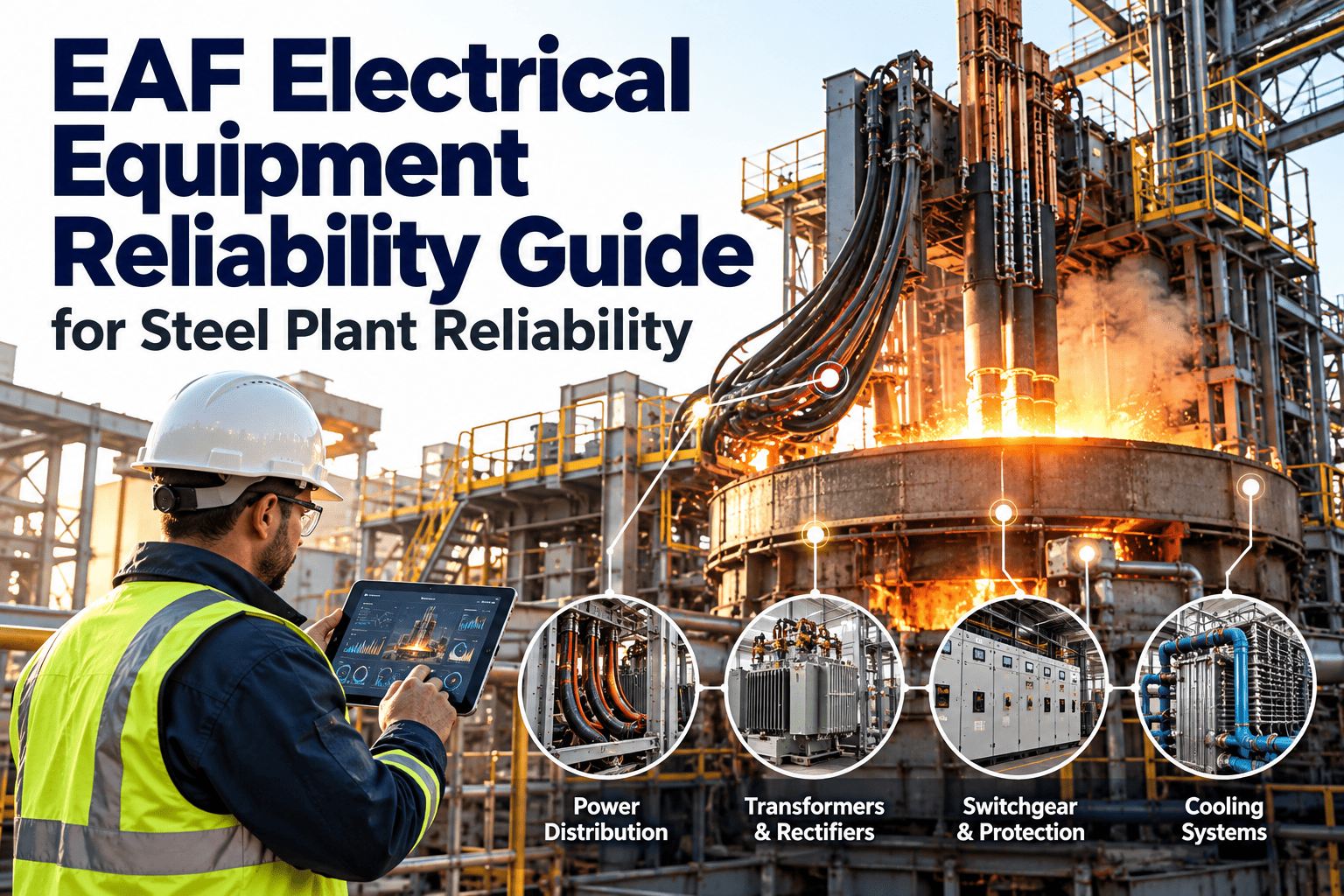
EAF Electrical Equipment Reliability Guide for Steel Plant Reliability Teams
Electrical faults in the furnace power path cause short, expensive stoppages. Inspection routes, thermal monitoring, current trends and transformer checks give you time to plan the repair instead of reacting to a trip. Oxmaint keeps every reading, defect and repair in one asset record.
Utility feed and MV switchgear
Furnace transformer and tap changer
Secondary bus and water-cooled cables
Electrode arms and clamps
Arc and melt
Why EAF Electrical Reliability Deserves Its Own Program
The electrical system runs at the edge
An electric arc furnace draws very high current in bursts, with constant load swings as scrap moves and arcs shift. Every component in the power path sees thermal cycling, vibration and electromagnetic stress on every heat.
Small faults grow quickly
A loose joint raises resistance, resistance raises heat, and heat loosens the joint further. Left alone, this loop ends in a burned connection, a cable failure or an unplanned power-off.
Mechanical wear in a melt shop is usually visible and audible. Electrical degradation is quiet, which is why reliability teams need scheduled measurement rather than relying on operator feel.
Where EAF Electrical Faults Actually Start
Most repeat electrical stoppages trace back to a short list of assets. The matrix below ranks typical fault areas by how often they appear in maintenance discussions and how hard they hit production. Adjust the placement using your own failure history.
Asset area
Likelihood
Production impact
Priority
Secondary bus and cable joints
High
High
Act first
Furnace transformer and tap changer
Medium
Very high
Act first
Furnace circuit breaker
Medium
High
Plan soon
Electrode regulation and hydraulics
High
Medium
Plan soon
Reactive compensation and filters
Medium
Medium
Monitor
The Fault Progression Timeline
Electrical faults follow a recognizable path from first sign to failure. Your goal is to catch the work at the earliest stage that instruments and inspections can reach.
1
Early signal. A joint runs a few degrees warmer than its twin on the same phase, or one phase shows slightly lower current for the same tap.
2
Trend confirms. The difference repeats across several heats and shifts. It is no longer noise.
3
Visible damage. Discoloration, oxidation, pitting on contact surfaces, or water leaks at a cable termination appear during inspection.
4
Functional failure. The furnace trips, a phase burns through, or the crew must cut power for an emergency repair.
Thermal Monitoring of the Power Path
Infrared inspection is the most practical first step for EAF electrical maintenance. It finds high-resistance connections without contact and without opening equipment. Compare like with like, and always record load at the time of the scan.
Thermal inspection checklist
- Scan MV switchgear, cable terminations and the furnace breaker at a repeatable load level.
- Compare each phase against the other two before judging absolute temperature.
- Record emissivity assumptions, distance and ambient conditions with every image.
- Scan bus tube joints, flexible connections and electrode clamp interfaces during a safe window.
- Check water-cooled cable inlet and outlet temperatures alongside flow readings.
- Rescan after every repair to prove the fix worked.
A temperature reading alone is a weak decision tool. A trend of temperature against load, logged for the same joint over months, tells you whether the connection is stable or deteriorating.
Reading Current Trends Across Phases
Furnace current data is already collected by the regulation system. The maintenance value lies in comparing it over time and between phases, not in watching it live.
Without trending
- Current is reviewed only after a trip.
- Phase imbalance is blamed on scrap mix.
- Electrode breakage and joint heating are treated as unrelated events.
- Repairs are logged as free text with no asset link.
With trending
- Phase current ratios are compared weekly for the same tap and program.
- Persistent imbalance triggers a joint and clamp inspection.
- Regulation response is reviewed when swings increase.
- Each finding becomes a work order on the exact asset.
Also watch power quality indicators such as flicker and harmonic content. Rising distortion can point to reactive compensation problems, failing filter capacitors or regulation issues, and it can stress upstream equipment.
Furnace Transformer Checks That Matter
The furnace transformer is the most expensive single item in the power path and has a long replacement lead time. Condition data is the only defense against surprise. The table lists common checks and how often teams schedule them.
| Check | What it reveals | Typical schedule basis |
|---|---|---|
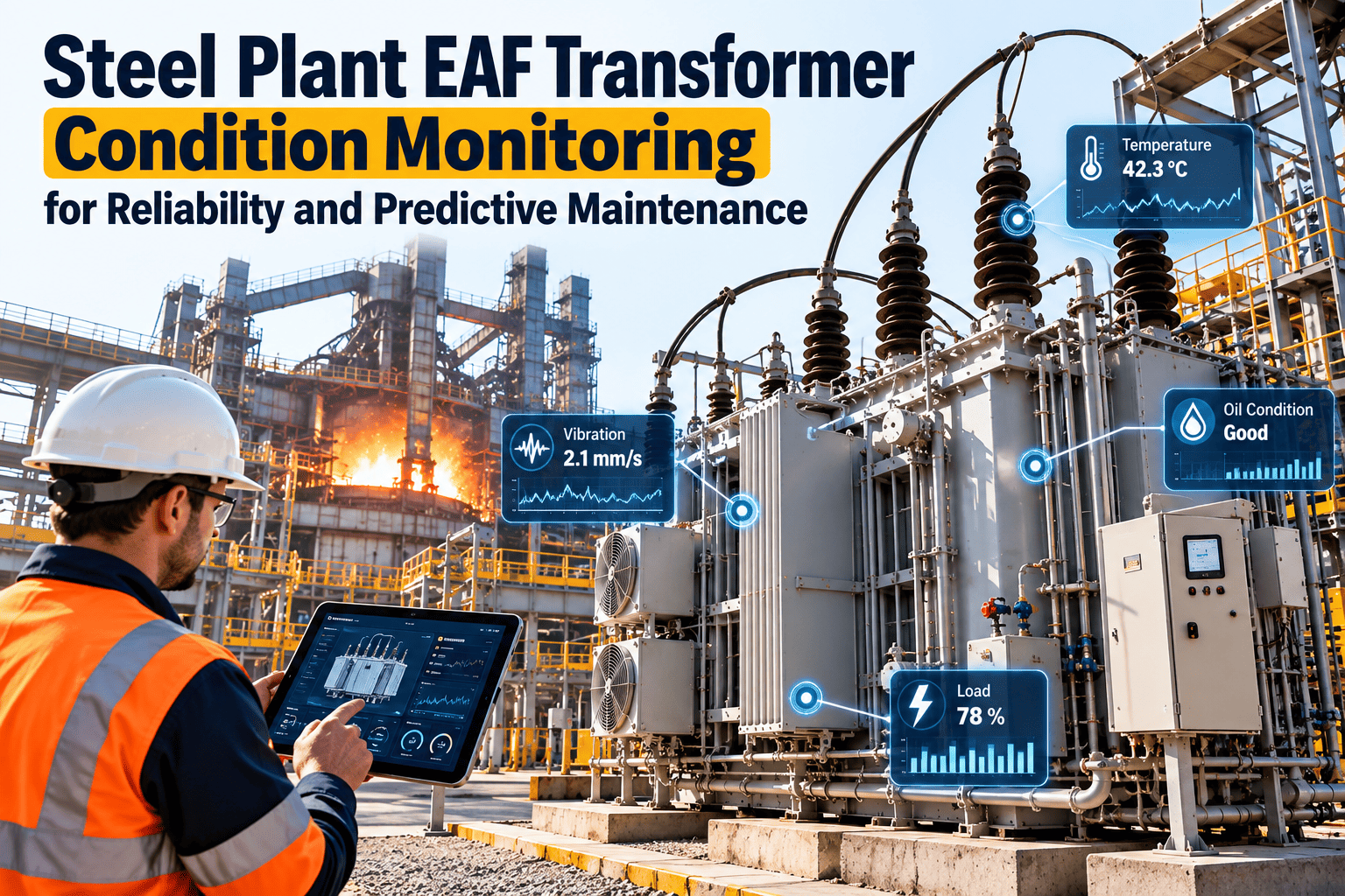
| Oil temperature and winding temperature | Overloading, cooling problems | Continuous, reviewed per shift |
| Dissolved gas analysis | Internal heating, arcing, insulation aging | Periodic sampling, more often after events |
| On-load tap changer operation count | Contact wear, service due point | Counter-based |
| Cooling water flow and radiator condition | Fouling, blocked heat exchange | Weekly walk-down |
| Bushing and connection inspection | Leaks, tracking, hot spots | Monthly plus thermal scan |
| Protection relay tests | Trip and alarm reliability | Annual or per site standard |
Tap changer duty in an EAF is heavy because operating programs change taps often. Track operations by count, not only by calendar, and align service work with planned outages.
Give Every Electrical Reading a Work Order
Oxmaint links inspection routes, findings and repairs to each furnace asset so nothing depends on memory or paper. Set up recurring checks and see the history in one place.
A Practical Inspection Rhythm by Frequency
Reliability programs fail when they try to inspect everything at once. Split the work by frequency so each visit is short, repeatable and assigned to a named role.
Every shift
Operators and electricians note alarms, unusual smells, water leaks at cable connections, transformer temperatures and any unexplained current swings. Findings go into a shift log that the next crew can see.
Weekly
Walk the power path, check cooling flows and return temperatures, review phase current comparisons and confirm that open electrical work orders are moving.
Monthly
Run thermal scans at agreed load, inspect bushings and terminations, review breaker operation counts and update the risk ranking of assets.
Planned outage
Retorque joints, replace worn contacts and clamp pads, service the tap changer when due, test protection and take oil samples where required.
Each layer feeds the next. A weekly comparison that shows a recurring difference between phases becomes a targeted item on the next outage list rather than a general inspection.
Power Quality and Its Effect on Equipment Life
Arc furnaces are demanding loads on the supply network. Rapid current changes create flicker, and non-linear behavior adds harmonic content. Compensation equipment such as static var systems and harmonic filters exists to contain those effects, and it needs maintenance of its own.
- Inspect filter capacitors for bulging, leaks and abnormal heating, and log unit-level replacements.
- Check cooling systems for compensation equipment, including fans, pumps and heat exchangers.
- Review harmonic and flicker records after any change in furnace program or scrap practice.
- Confirm that protection settings still match the installed configuration after modifications.
When compensation equipment degrades, the furnace transformer and upstream switchgear often carry the consequences. Treat these assets as part of the same reliability chain, not as separate utility items.
Common Root Causes Behind Repeat Electrical Stops
| Root cause | How it shows up | Preventive response |
|---|---|---|
| Loose or oxidized joint | Local heating, discoloration, phase imbalance | Defined torque procedure, contact cleaning, rescan after repair |
| Cooling loss on cables or arms | Rising return temperature, insulation damage | Flow checks, filter cleaning, alarm verification |
| Contamination and dust | Tracking on insulators, moisture ingress | Cleaning schedule, sealing checks in enclosures |
| Mechanical vibration | Fatigue at flexible connections and supports | Visual inspection of supports and flexible links |
| Switching wear | Slow breaker operation, contact erosion | Count-based service and timing tests |
| Skipped or undocumented work | Same fault returns with no history | Work orders with required fields and closure checks |
Spare Parts and Repair Readiness
Even a perfect inspection program will find faults that need parts. Stock decisions should reflect failure history and lead time, not habit.
Keep on the shelf
Contact sets, clamp pads, cable connection hardware, water hoses and fittings, relay modules and consumables that fail often and repair fast.
Plan with suppliers
Transformer components, large bus sections and specialist assemblies with long lead times. Document specifications and contact details in the asset record.
Link parts to assets and work orders so usage data shows which items to stock deeper and which to drop from inventory.
Shift Handover and Documentation Habits
Electrical faults often surface at night or on weekends, when the person who knows the history is absent. A short structured handover reduces that gap.
- Record open defects with asset name, symptom and current risk level.
- Note any temporary measures, such as reduced power settings, and who approved them.
- Attach photos and thermal images to the work order, not to personal phones.
- Close every completed job with cause, action and verification result.
These habits cost minutes per shift and save hours when the same fault reappears. They also give auditors and insurers a clear record of maintenance discipline.
Circuit Breakers, Switchgear and Protection
Furnace breakers operate far more often than distribution breakers. Wear is driven by switching count and fault duty rather than age.
Operation counters
Log switching operations and compare them with the manufacturer service interval.
Mechanism checks
Inspect springs, linkages, lubrication and timing test results at each outage.
Protection settings
Record relay settings and test dates so changes are traceable after any event.
Electrode System and Regulation
The electrode arms, clamps and hydraulic regulation form the link between electrical design and melt behavior. Poor clamp contact creates heat at the interface. Slow or unstable regulation increases current swings and stresses upstream equipment.
- Inspect clamp pads, contact faces and current-carrying surfaces at every scheduled stop.
- Check hydraulic response, valve condition and leaks on the regulation circuit.
- Verify water cooling on arms and cables, including flow and return temperature.
- Record electrode consumption and breakage next to electrical findings for pattern analysis.
Building a Failure History That Prevents Repeats
Most plants repair well and document poorly. When a burned joint is fixed and logged as a generic electrical repair, the same failure returns because nobody can see the pattern. A usable failure record has five parts.
Asset. The exact joint, cable, breaker or transformer, not just the furnace.
Symptom. What was observed and how it was detected.
Cause. Root cause selected from a consistent list, such as loose connection, contamination, cooling loss or overload.
Action. The repair, parts used and labor time.
Follow-up. Verification scan or test, and any change to the inspection plan.
With this structure, the same failure code appearing three times on one phase becomes a decision to redesign the joint or change the torque procedure, not another repair ticket.
How Oxmaint Supports EAF Electrical Maintenance
Oxmaint is built for maintenance teams that need structure without heavy administration. In an EAF environment the useful capabilities are practical ones.
| Maintenance need | Oxmaint capability |
|---|---|
| Scheduled thermal scans and inspection routes | Preventive maintenance schedules and inspection checklists on mobile |
| Repair of a hot joint or worn breaker | Corrective work orders linked to the asset |
| Transformer and switchgear records | Asset register with history, documents and readings |
| Spare contacts, clamps and cable sets | Inventory tracking with usage on work orders |
| Outage planning | Scheduling and backlog visibility for planned stops |
| Management review | Reports and dashboards on repeat failures and work completion |
Condition data from thermal cameras, oil labs or plant systems can inform triggers for work, so predictive and condition-based workflows sit on top of the same asset record.
Turning Outage Findings Into Next Quarter's Plan
Every outage produces information that is easy to lose. Measured joint resistance, worn contact dimensions, oil results and inspection photos should feed the next plan directly.
- Compare as-found and as-left readings for each serviced joint and breaker.
- Flag any asset that needed more work than planned and adjust its interval.
- Review parts consumed and update minimum stock levels.
- Convert deferred items into scheduled work orders with a target date.
Over a few cycles, this loop moves the electrical team from reacting to trips toward scheduling work on the assets that history says are most likely to fail.
KPIs for EAF Electrical Reliability
Electrical delays per month
Count and minutes, split by asset area.
Inspection completion
Scheduled scans and checks finished on time.
Repeat failure rate
Same asset and cause within a set period.
Planned versus emergency work
Share of electrical work planned in advance.
Choose a small set, review it monthly, and tie each metric to an owner. Metrics without owners tend to be reported and ignored.
Frequently Asked Questions
How often should EAF electrical connections be scanned?
Follow your site risk and OEM guidance, and scan more often on joints with a history of heating. Log results in Oxmaint to see trends.
Can current data predict electrical failure?
It can flag imbalance and abnormal swings that point to joints, clamps or regulation. It works best combined with thermal scans and inspection.
What transformer data should reliability teams track?
Temperatures, dissolved gas results, tap changer operations, cooling condition and protection tests, all tied to one asset record.
Do we need sensors before using a CMMS?
No. Start with inspection routes and structured work orders, then add condition data as it becomes available.
How do we see it for our furnace?
You can book a demo and map your power path assets during the session.
Protect Every Heat With a Clear Electrical Maintenance Record
Bring inspections, thermal findings, transformer checks and failure history into one steel plant CMMS. Start with your highest-risk furnace assets and build from there.