A coil doesn't get rejected because a stand breaks down — it gets rejected because the roll gap quietly held a shape it shouldn't have, and nobody caught the drift until the shapemeter flagged edge wave three passes too late. Crown and wedge are the two profile parameters that decide whether a coil ships to a customer paying premium for automotive or appliance grade steel, or gets downgraded to a lower-spec buyer at a fraction of the price. Every micron of uncorrected crown drift and every degree of asymmetric wedge compounds stand after stand until the finishing mill runs out of bending force, shifting stroke, and roll gap correction to fight its way back to target. Steel plants that hold shape within tolerance across a full roll campaign are not running better rolls — they are running a tracked discipline where actuator position, roll wear, and coolant balance all report into the same system, which is exactly what plants build with the OxMaint CMMS platform. From there, every stand on the mill gets its own shape record instead of a shared spreadsheet nobody trusts.
Shape Control Software for Crown, Wedge & Full-Width Profile
Connect shapemeter readings, actuator position, roll wear, and coolant balance into one CMMS record — so profile drift gets caught at the stand, not at the customer's incoming inspection.
Why Crown and Wedge Are Two Completely Different Problems
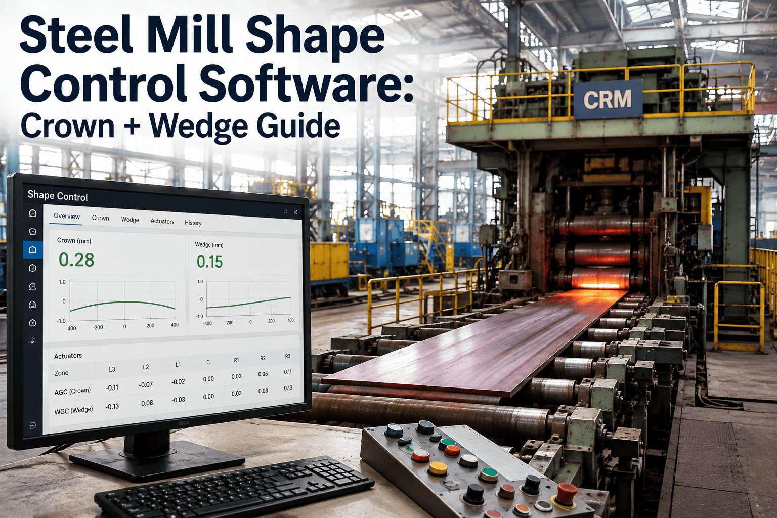
Most mill floors talk about "shape" as one thing. It isn't. Crown is a symmetric problem — the strip is thicker in the center than at the edges, and it is fixed with roll bending, work roll shifting, or continuously variable crown rolls. Wedge is an asymmetric problem — one side of the strip runs thicker than the other, and it comes from uneven roll wear, thermal camber that differs drive-side to operator-side, or a stand that has drifted out of level. Treating both with the same correction logic is exactly how plants end up chasing a fault for three shifts before someone finally separates the two signals.
Crown Control
Center-to-edge thickness variation, usually described as a percentage of strip thickness. Corrected through work roll bending force, roll shifting stroke on CVC and UVC rolls, and roll gap adjustment at the reduction screws. Upstream stands carry most of the crown-correction burden because they still have bending force in reserve.
Wedge Control
Drive-side versus operator-side thickness difference, driven by uneven work roll wear, unequal thermal camber, or a levelling fault at the housing. Corrected with differential roll bending, tilt adjustment at the screws, and — when the root cause is mechanical — a roll change rather than a process tweak.
The Shape Control Signal Chain — From Shapemeter to Work Order
A shapemeter roll or set of profile gauges reads strip tension distribution across the width, tens of times per second, on every stand that carries one. That signal only creates value when it closes a loop — first correcting the process in real time, then, when the correction pattern itself looks abnormal, opening a maintenance work order before the defect becomes a customer claim. The five-stage chain below is what a disciplined shape control program actually runs on the floor.
Profile Measurement
Shapemeter roll or optical gauge samples tension and thickness distribution across strip width at the exit of each equipped stand, continuously through the pass.
Deviation Classification
Signal is split into symmetric component (crown) and asymmetric component (wedge) so the correct actuator group responds instead of a blended, imprecise correction.
Fast-Loop Correction
Bending force, roll shift position, or screw tilt adjusted under load within the pass. Fast loop handles the coil in progress without stopping the mill.
Actuator Load Trending
Percentage of available bending force or shift stroke used to hold target logged against every coil. Rising trend flags equipment drift long before shape actually fails.
Maintenance Work Order
When actuator load or correction frequency crosses threshold, a work order is auto-raised against the specific roll, bearing, or coolant header — not a generic "check shape" ticket.
Stop Letting Shape Faults Trace Back to a Roll Nobody Was Watching
OxMaint links every stand's actuator load, roll campaign life, and coolant header condition to the shape signal — so drift gets a work order, not a customer claim.
What Untracked Shape Drift Actually Costs a Mill
The visible cost of a shape claim is the credit note. The invisible cost is everything that happened for weeks before the claim — coils running inside spec but consuming 85 percent or more of available bending force to stay there, coolant headers running unbalanced and quietly building thermal wedge, and a roll campaign that should have been pulled a week earlier sitting in the stand because nobody was watching the trend. The breakdown below is what that invisible cost typically looks like across a rolling year.
Direct credit notes and rework costs on coils shipped outside crown or wedge tolerance for premium grade orders.
Product diverted from premium automotive or appliance spec to a lower-value grade when shape drifts inside acceptable but not premium range.
Bending cylinders, shifting drives, and screw motors running near saturation for extended periods, shortening component life.
Rolls pulled early on suspicion of wear, or left in too long chasing a correction that mechanical wear can no longer deliver.
Common Root Causes Behind a Wedge Fault — And Where They Actually Start
When a wedge fault shows up at the exit shapemeter, the instinct on most floors is to blame the stand where it was measured. In practice, wedge is rarely created where it is caught — it is usually inherited from one or two stands upstream and simply becomes visible once the strip narrows and thins enough for the shapemeter to resolve it clearly. Tracing it back without a logged history means walking the mill stand by stand, which is exactly the hours-long investigation a tracked program is built to avoid.
Uneven Roll Wear
One work roll wears faster than its pair due to unequal load distribution or a hard-spot in the incoming slab. The wear itself is gradual, but the wedge it introduces can appear suddenly once the roll crosses a wear threshold the bending system can no longer fully compensate for.
Coolant & Thermal Camber Drift
Drive-side and operator-side work roll temperatures diverge when coolant flow is not balanced across the width, changing the effective roll diameter unevenly. This thermal component of wedge builds and decays over minutes, not passes, which is why it is often missed by fast-loop correction alone.
Reading the Board — What a Tracked Shape Program Looks Like Mid-Campaign
The board below shows a six-stand hot strip finishing train mid-campaign, with every stand's shape status, actuator load, and next action visible from one screen instead of a control-room trend chart nobody outside the pulpit ever sees.
Reactive Shape Correction vs a Tracked Shape Program
Nearly every mill already corrects shape in real time — that part is standard process control. The gap is in what happens to the data afterward. A tracked program keeps the correction history against equipment condition; a reactive program throws it away at the end of the shift. The comparison below is what plants typically see in the first operating year after connecting shapemeter data to their CMMS.
| Program Element | Reactive (Process-Only) | Tracked (CMMS-Connected) | Typical Impact |
|---|---|---|---|
| Premium Grade Yield | 82–88% of order volume qualifies | 94–97% of order volume qualifies | +8% premium yield |
| Roll Change Timing | Fixed calendar interval regardless of wear | Triggered by actuator load and wear trend | +15% roll life captured |
| Root-Cause Time | Hours to trace which stand caused a fault | Minutes, traced to stand and component | 70% faster diagnosis |
| Customer Shape Claims | Recurring, several per quarter typical | Rare after first tracked campaign | Claims reduced sharply |
| Actuator Component Life | Frequent saturation, early replacement | Load trended, replaced on condition | Longer service intervals |
The Six CMMS Practices Behind a Disciplined Shape Program
Mills that consistently hold crown and wedge inside premium tolerance across a full roll campaign are not relying on a better shapemeter. They are running the same six practices inside their CMMS, enforced through scheduled work orders rather than left to whichever operator happens to notice a trend on shift.
Actuator Load Trending
Bending force and shift stroke logged as a percentage of available range against every coil, not just when a fault occurs. Rising baseline load is the earliest signal of roll or bearing wear.
Crown / Wedge Split Logging
Shape deviation recorded as separate symmetric and asymmetric components against each coil ID, so a claim investigation starts with data instead of a guess about which stand was responsible.
Coolant Header Balance Check
Flow readings across headers compared stand to stand. A single restricted nozzle can build enough thermal camber difference to register as wedge two stands downstream.
Roll Wear Condition Record
Work roll and backup roll wear logged against tonnage rolled and actuator load carried during the campaign, feeding the next roll grinding schedule instead of a fixed interval.
Stand Level & Alignment Audit
Housing level and roll gap parallelism checked on the stands most prone to wedge drift. A small alignment fault compounds through every downstream stand.
Closed-Loop Claim Traceback
Every customer shape claim traced back through the coil's actuator load and roll condition history at the time it was rolled, closing the loop from complaint to root cause.
What a Tracked Shape Program Returns Across a Rolling Year
The figures below reflect what steel plants document after moving shape data out of the process control screen alone and into a CMMS record connected to equipment condition. They compound across a full roll campaign and accelerate as the historical baseline builds.
More coil volume qualifying for premium automotive and appliance grade instead of being downgraded on shape.
Claim investigations resolved in minutes using logged actuator and roll condition data instead of shift-log guesswork.
Roll changes triggered by condition and actuator load trend rather than a fixed calendar interval.
Coolant and alignment root causes closed out permanently instead of being process-compensated coil after coil.
Frequently Asked Questions
Every Shape Correction Should Leave a Record, Not Just a Trend Line
The mills holding crown and wedge inside premium tolerance across full roll campaigns all run one system for shapemeter data, actuator condition, and roll wear history — start building that record today.