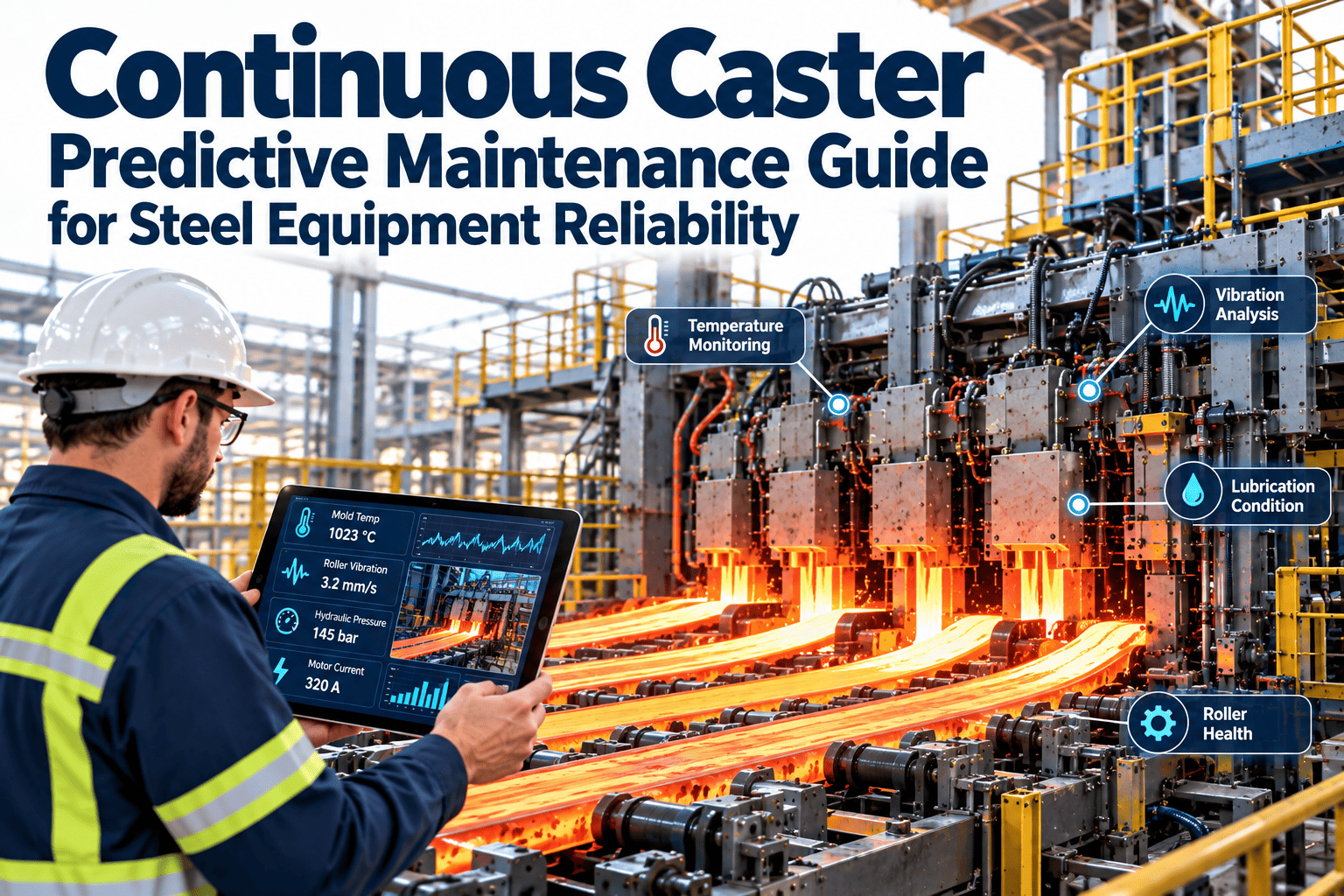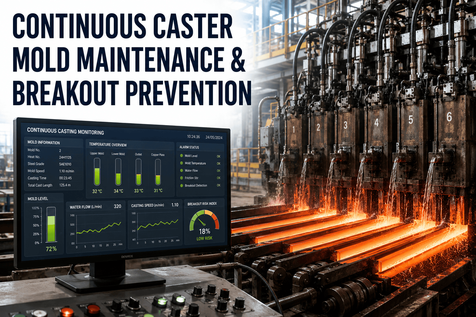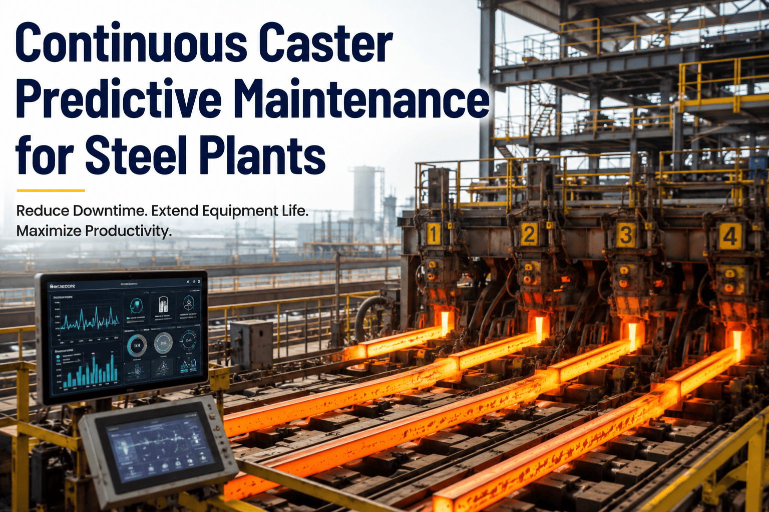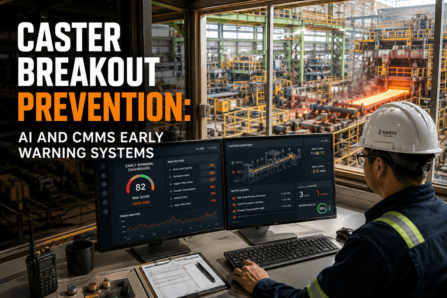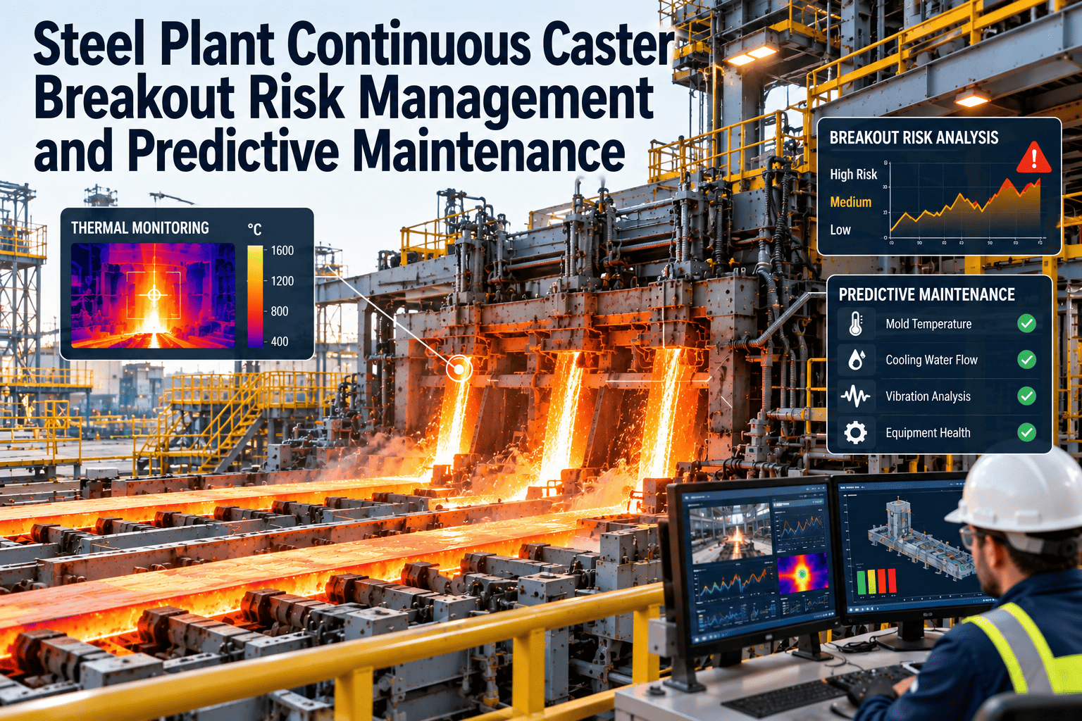
A breakout at the continuous caster is the one failure mode every melt shop plans its maintenance calendar around, because when the solidifying shell tears and liquid steel escapes the mold or strand, the line can sit idle for a full shift and the cleanup bill runs into six figures before a single tonne of lost production is counted. Breakout risk is never caused by one component — it builds across mold condition, thermal behavior, roll and segment wear, and spray cooling performance at the same time, which is why treating it as a single checklist item instead of a layered defense is where most prevention programs fall short. Reliability teams that manage this well track all four layers inside one asset system, often a steel-plant CMMS such as Oxmaint, rather than four separate spreadsheets that never talk to each other.
Every breakout has a maintenance signature — if you're tracking the right things
Sticker breakouts, mold friction breakouts and shell thinning events do not appear without warning. Mold thermocouples, roll bearing vibration, spray nozzle flow and inspection history all carry the early signal — the discipline is connecting them to a single risk picture before the shell tears.
Why breakout risk resists a single fix
A breakout is the end state of several possible failure paths converging at once, not a single root cause repeating itself. That is what makes it hard to manage with one inspection checklist or one sensor type.
A mold that is perfectly maintained can still see a breakout if a segment roll below it has drifted out of alignment and thinned the shell after it left the mold. A fully instrumented thermocouple grid provides no protection if half the sensors have failed silently and nobody flagged the gap on the maintenance plan. Managing breakout risk well means accepting that no single layer is sufficient on its own, and building overlapping coverage instead of relying on whichever layer happens to be easiest to monitor.
The four defense layers
Rather than one long checklist, breakout prevention is easier to manage as four layers, each catching what the layer before it missed.
Mold condition & oscillation PM
Copper plate taper measurement every campaign, oscillation stroke and frequency calibration, and mold powder feed verification. This layer prevents the conditions that lead to a tear from developing in the first place, rather than catching them once they start.
Real-time thermal & breakout detection
Mold thermocouple arrays tracking heat flux across every row, feeding a breakout detection system that flags a sticker pattern and slows or stops the strand before the tear propagates out of the mold. This layer only works if every thermocouple in the grid is verified functional — a dead sensor is a blind spot in the safety net.
Segment & roll condition monitoring
Roll bearing vibration, segment gap measurement and spray nozzle flow verification below the mold, where shell thinning or bulging from a misaligned segment can reopen risk even after the strand has solidified past the mold exit.
Inspection discipline & corrective workflow
Scheduled visual and dimensional inspections logged against the specific mold and segment asset, with a corrective work order that closes the loop the same shift a deviation is found — not at the next planned outage.
What the mold thermocouple grid is actually telling you
A slab caster mold typically carries several dozen to well over a hundred embedded thermocouples arranged in rows across the copper plates. Under normal casting, readings across a row stay within a tight band of each other; a developing shell tear shows up first as a localized cluster of rows running hotter than their neighbors, then accelerating as the sticker propagates upward toward the mold exit.
The pattern above is the classic signature reliability teams train operators to recognize: a widening, rising cluster moving across adjacent columns row over row. Catching it depends entirely on the thermocouple grid being fully instrumented — when sensors have failed and no one has flagged the gap, the same pattern can develop in a blind spot with no alarm at all.
This is exactly why thermocouple health tracking belongs on the maintenance plan as its own line item, not as an afterthought to the breakout detection system's software configuration. Each sensor should carry a functional-status flag alongside its live reading, so a maintenance planner can see at a glance which positions in the grid are currently blind rather than discovering it during a post-incident review.
KPIs that show the program is reducing real risk
A breakout prevention program that only measures breakout count is measuring too late — by the time that number moves, the damage is already done. Leading indicators give reliability teams a way to see the program working before an incident, not just after one is avoided.
Root causes that keep showing up across breakout investigations
No two breakouts are identical, but post-event investigations across the industry tend to trace back to a short list of recurring contributors. Reliability teams that keep a running log of these contributors across every near-miss, not just every actual breakout, build a much richer picture of which failure path is most likely to recur at their specific caster than any generic industry list can provide.
Human factors: training and escalation discipline
Instrumentation and CMMS integration only close half the gap — the other half is whether operators and maintenance crews trust and act on what the system tells them. A caster crew that has been trained to recognize a rising thermocouple cluster pattern reacts in seconds; one that has only ever seen a generic alarm tends to wait for a second confirmation before adjusting speed, and that hesitation is exactly the window a sticker breakout needs to propagate. Regular tabletop reviews of past near-misses, using the actual thermocouple traces rather than a generic training slide, keep that recognition sharp long after the last real event has faded from memory.
Escalation paths matter just as much as recognition. A deviation that routes only to the pulpit operator, with no parallel alert to the shift maintenance lead, puts the entire response on one person during the highest-pressure moment of the shift. Routing the same signal to both roles simultaneously — and logging who acknowledged it and when — turns the response into a team action rather than a single point of failure.
Put mold, thermal, roll and inspection data in one place
A breakout risk picture split across four systems is a breakout risk picture nobody is actually watching in real time.
Building the corrective workflow around a deviation
Detecting a deviation is only half the job — what happens in the minutes and hours after matters just as much for whether it stays a near-miss or becomes a breakout.
Plants with a mature program treat every confirmed near-miss as data, not just a saved shift. A thermocouple cluster that trended toward alert but was caught by a speed reduction still gets logged, reviewed and folded into the next campaign's inspection plan — the same way a caught bearing defect informs the next lubrication schedule. Skipping that review step means the plant keeps rediscovering the same precursor pattern instead of tightening its detection thresholds around it.
What good breakout risk management looks like in a CMMS
The plants that reduce breakout frequency year over year are not necessarily running more sensors — they are running a system where every sensor, inspection and repair for the caster lives against the same asset record. A separate breakout detection system, a separate vibration monitoring dashboard and a separate paper inspection log each do their individual job well, but none of them tell the shift lead the combined risk picture across all three at the moment it matters most.
Bringing that data together does not require replacing the specialized instrumentation already in place. The breakout detection system keeps doing real-time thermal analysis; the vibration monitoring system keeps doing spectral analysis on segment bearings. What changes is that both systems' outputs, along with inspection results and work order history, write back to the same caster and mold asset records — so a maintenance planner reviewing a mold's history sees taper measurements, thermocouple health and prior corrective actions in one place instead of stitching together three exports.
Oxmaint brings mold thermocouple health, segment vibration trends, spray nozzle verification and inspection records into one caster asset record, so a deviation in any layer automatically generates the work order and routes it to the right person — instead of living in a standalone dashboard that nobody opens mid-shift.
Frequently Asked Questions
What causes most continuous caster breakouts?
Sticker-type breakouts from shell-to-mold friction and mold powder irregularities are among the most common, alongside copper plate wear past taper limits and segment misalignment below the mold.
How much warning does a mold thermocouple grid typically give before a breakout?
A developing sticker pattern usually shows up as a localized thermocouple cluster deviation, giving a window measured in minutes rather than hours — which is why the detection system needs every sensor functional, not just most of them.
Is breakout risk only a mold issue?
No. Segment roll misalignment, spray cooling blockages and strand guide wear below the mold can thin or reopen a shell that solidified normally, which is why risk management needs to cover the full strand, not just the mold.
Can Oxmaint integrate directly with our existing breakout detection system?
Oxmaint is built to bring thermocouple health, segment condition and inspection data into one asset record and auto-generate work orders on deviation. Book a Demo to walk through your caster's specific instrumentation.
How often should mold taper be measured to manage breakout risk?
Taper should be measured at defined points after every campaign, or on a fixed heat-count interval, and logged against the mold's own wear baseline rather than a generic fleet average.
See breakout risk before the shell tears, not after
Bring mold, segment, spray and inspection data together in one caster asset record with Oxmaint.
Free trial available · No credit card required