Pumps and compressors are the circulatory system of a steel plant — cooling water that keeps refractory alive, hydraulic pressure that controls roll gap to micrometre precision, and process gas compression that feeds every furnace in the facility. When any of these systems fail, the production consequence is immediate. Sign in to OxMaint to manage your pump and compressor PM schedules, vibration trending, and condition-based maintenance records, or book a demo to see the predictive analytics workflow for rotating equipment.
Material Handling / Steel Plant
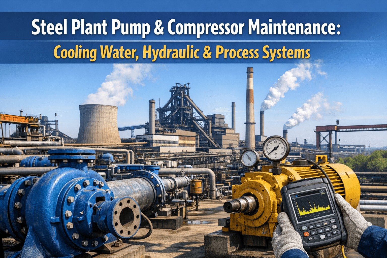
Steel Plant Pump & Compressor Maintenance: Cooling Water, Hydraulic & Process Systems
The maintenance frameworks, monitoring techniques, and predictive analytics that keep cooling water pumps, hydraulic power units, and process gas compressors running reliably — in the one environment where they are pushed hardest.
1–6
Months early that vibration monitoring detects bearing failure — before failure actually occurs
$50B
Annual industrial downtime cost — pumps and compressors are among the top contributors
24/7
Monitoring required for critical assets like cooling water and hydraulic systems feeding continuous processes
3–5x
Cost of reactive pump repair vs. planned replacement — the true cost of deferred maintenance
The Three Critical Systems — and Why Each Fails Differently
Cooling water pumps, hydraulic power units, and process gas compressors serve different functions, operate under different conditions, and develop failures through different mechanisms. A maintenance programme that treats them identically will underserve all three. Understanding the distinct failure modes of each is the foundation of a system-specific maintenance approach.
Function
Continuous circulation of cooling water to furnaces, casters, rolling mill bearings, and refractory systems. A single cooling pump trip on a blast furnace stave system can cause stave burnout within minutes.
Primary Failure Modes
Impeller cavitation from low NPSH, bearing wear from misalignment, seal failure from water hammer, impeller erosion from scale and abrasive particles in cooling circuits.
Monitoring Priority
Flow rate and differential pressure, bearing vibration and temperature, mechanical seal condition, motor current draw — all at continuous 24/7 monitoring for critical cooling circuits.
Function
High-pressure oil supply for rolling mill roll gap control, screw-down systems, side guides, and caster withdrawal and straightening machines. Servo valve systems require oil cleanliness to ISO 4406 Class 16/14/11 or better.
Primary Failure Modes
Fluid contamination above ISO cleanliness limits causing servo valve stiction, pump vane and piston wear from particulate, seal degradation from thermal cycling, and water ingression causing oil emulsification.
Monitoring Priority
ISO 4406 oil cleanliness by particle counter, pump pressure and flow, fluid temperature, filter differential pressure, servo valve response time — oil analysis monthly on critical HPUs.
Function
Blast furnace top gas recovery, coke oven gas compression for distribution, and nitrogen compression for inert gas purging of ladles and tundishes. Process gas compressors handle toxic and flammable gas streams under continuous load.
Primary Failure Modes
Reciprocating compressor valve failure from polymer deposits and fatigue, bearing degradation from lubricant contamination, piston ring wear, and seal gas system failure causing hazardous gas release.
Monitoring Priority
Suction and discharge pressure and temperature, valve differential temperature (detecting failing valves), bearing vibration, oil analysis for wear metals, seal gas pressure and flow.
Vibration Monitoring: The Universal Diagnostic for Rotating Equipment
Vibration analysis is the most sensitive early-warning tool available for pumps and compressors. Each failure mode produces a characteristic vibration signature at a predictable frequency — and those signatures appear weeks to months before the failure is visible or audible. The table below maps the critical failure modes in steel plant rotating equipment to their vibration frequency signatures and detection techniques.
| Failure Mode |
Vibration Signature |
Detection Method |
Typical Lead Time |
Action Threshold |
| Bearing Fault (early) |
High-frequency sub-harmonics — BPFO, BPFI, BSF frequencies in envelope spectrum |
Envelope analysis / high-frequency acceleration |
1–6 months |
Initiate trending — no immediate action |
| Imbalance |
1× RPM dominant peak in velocity spectrum |
Overall vibration + FFT spectrum |
Weeks to months |
ISO 20816 — plan balancing at next window |
| Shaft Misalignment |
2× RPM dominant, often with axial component |
Velocity spectrum — axial and radial |
Weeks |
Laser alignment check and correction |
| Cavitation |
Broadband noise — high-frequency random excitation |
High-frequency vibration + acoustic emission |
Hours to days |
Immediate — check NPSH, suction conditions |
| Compressor Valve Failure |
Temperature differential between inlet/outlet valves — rising delta-T on affected valve |
Valve temperature monitoring + pressure pulsation |
Days to weeks |
Plan valve inspection at next outage opportunity |
| Gear Mesh (HPU gearbox) |
Gear mesh frequency + sidebands in acceleration spectrum |
FFT spectrum — acceleration |
Weeks to months |
Oil analysis confirmation + trend acceleration |
Track Vibration Trends and Trigger PM Work Orders Automatically in OxMaint
Configure vibration alarm thresholds per asset, log periodic measurements from the mobile app, and let OxMaint auto-generate a corrective work order when a trend crosses its warning level — before the bearing fails.
Maintenance Task Framework by System
Daily
Check cooling water pump flow indicators and differential pressure gauges against normal operating range
Verify HPU reservoir level, temperature, and system pressure on all critical circuits
Inspect compressor seal gas pressure and flow — any deviation is a safety-critical finding
Check for external leaks — hydraulic fluid on floor, water weeping from pump shaft seal, oil mist at compressor connections
Confirm duty/standby pump switchover has occurred on schedule (80/20 or 70/30 rotation to prevent false brinelling)
Monthly
Vibration route survey — all critical and secondary pumps and compressors with handheld data collector
Oil sample collection for hydraulic systems and compressor sumps — send for particle count, viscosity, wear metals, water content
Cooling water pump performance curve check — compare actual flow/head against rated pump curve for impeller wear assessment
Cooling circuit water quality check — pH, hardness, biocide concentration, scale inhibitor levels
HPU filter differential pressure review — replace elements approaching bypass threshold before bypass occurs
Annual / Outage-Linked
Mechanical seal replacement on critical cooling pumps — do not wait for failure on continuous-duty critical service machines
Coupling alignment check and laser alignment correction — misalignment is the leading cause of premature bearing and seal wear
Compressor valve overhaul — disassemble, inspect plates, springs, and seats; replace on condition or at defined interval
Hydraulic oil full drain and refill for systems with confirmed contamination or oil degradation beyond acceptable limits
Impeller inspection and measurement — compare to OEM wear limits, assess for cavitation damage, balance check after refitting
Duty/Standby Management: The Pump Failure That Nobody Plans For
Steel plants run critical pump systems on duty/standby configurations — one pump running, one on immediate standby. The common assumption is that the standby pump is ready. In practice, without structured management, standby pumps develop false brinelling — static bearing damage caused by vibration transmitted from the running duty pump through the shared baseplate — and seize on startup at the worst possible moment. A structured duty/standby rotation programme, logged as recurring work orders in OxMaint, eliminates this failure mode.
Rotation Schedule
Switch duty and standby on an 80/20 or 70/30 run-hour ratio — not calendar-based. Log every switchover as a completed work order with run-hour confirmation. Standby pump must accumulate run hours to maintain bearing lubrication film and prevent static corrosion on seals.
Standby Vibration Check
Take vibration readings immediately after standby pump starts and compare against the baseline for that pump. Post-startup vibration above baseline indicates developing false brinelling damage that requires early intervention. Do not log standby startup as a routine event — log it as a recorded check with measurement data.
Auto-Start Test
Monthly auto-start test confirms the standby pump's automatic start signal, check valve, and isolation valve are all functional. A standby pump that starts on schedule but fails on auto-start has no operational value. Record the test result as a work order completion — not a verbal confirmation.
"
The most consistent pump failure pattern I see in steel plants is not the bearing that vibration monitoring missed — it is the standby pump that was never properly tested and the cooling system that had no redundancy plan when the duty pump failed. Every critical cooling and hydraulic pump needs three things documented in the CMMS: a vibration baseline taken when the machine was in known good condition, a duty/standby switchover schedule with completion records, and a documented emergency response procedure. Without those three records, a pump maintenance programme is not a programme — it is a collection of individual work orders with no system behind them. The difference between steel plants that avoid catastrophic pump failures and those that experience them is almost always documentation quality, not monitoring technology.
OxMaint for Pump & Compressor Maintenance
PM Schedule
System-Specific PM Templates
Pre-configured PM task templates for cooling water pumps, hydraulic power units, and process gas compressors — with correct task frequencies, measurement fields, and acceptance criteria for each system type.
Vibration
Vibration Measurement Logging & Trending
Log vibration readings from the OxMaint mobile app on the route. Alarm thresholds configured per asset per measurement point. Trending view shows how vibration is moving over time — the early warning the maintenance team needs before failure.
Oil Analysis
Oil Sample Records & Trending
Record lab results for every oil sample against the asset and date. Trend particle count, water content, and wear metals across sample intervals. Condition-based oil change decisions backed by data — not calendar guesswork.
Duty/Standby
Switchover & Auto-Start Work Orders
Recurring work orders for duty/standby switchover and monthly auto-start tests — automatically generated at configured intervals, assigned to the responsible technician, with mandatory measurement fields that cannot be skipped at closure.
Cooling Water Trips Stop Furnaces. Hydraulic Failures Stop Rolling. OxMaint Keeps Both Running.
Structured PM schedules, vibration trending, oil analysis records, and duty/standby management — all in one system that turns condition data into planned maintenance before the failure happens.
Frequently Asked Questions
How often should vibration readings be taken on steel plant pumps and compressors?
For critical assets — cooling water pumps feeding blast furnace stave systems or hydraulic pumps on rolling mill roll gap control — continuous online monitoring is the appropriate standard, with fixed vibration sensors streaming 24/7 data. For secondary pumps and compressors, a monthly route survey using a handheld data collector is the industry minimum, with high-criticality assets on a weekly route. The key is consistency: a pump measured monthly for 12 months generates a trend that detects bearing degradation. A pump measured only when problems are suspected generates no trend at all.
Sign in to OxMaint to configure vibration measurement schedules and alarm thresholds per asset.
What are the most common causes of cooling water pump failure in steel plants?
Cavitation from inadequate NPSH (net positive suction head) is the most common cause of accelerated impeller damage — it typically develops when suction strainers partially block, inlet valves are throttled, or cooling circuit flow demand increases beyond the original pump design point. The second most common cause is mechanical seal failure from water hammer events — pressure shocks generated when pump auto-start against a closed discharge valve, when control valves fast-close, or when a standby pump starts into a running system. Bearing failure from misalignment is the third most common, and the most preventable — laser alignment at every mechanical seal replacement eliminates a large proportion of premature bearing failures.
What oil cleanliness standard should steel plant hydraulic systems maintain?
Servo valve systems — roll gap control, screw-down, withdrawal and straightening machines — require ISO 4406 cleanliness of 16/14/11 or better. General hydraulic circuits operating with proportional valves require 17/15/12. Systems with standard directional valves can accept 18/16/13. These targets must be maintained continuously, not just at oil change intervals. Particle counting should be performed monthly on critical servo valve systems, and a corrective work order raised whenever results exceed the target class. Hydraulic oil that exceeds its cleanliness target is the leading cause of servo valve stiction in rolling mills — a single failed servo valve on a roll gap system can produce strip thickness variation that generates quality rejects before any alarm activates.
Book a demo to see oil analysis trending and threshold-triggered work orders in OxMaint.