Steel equipment runs hot, dirty, heavy and continuous, so a single failed fan, gearbox or hydraulic unit can interrupt an entire process chain. Reliability centered maintenance helps a steel plant decide which assets matter most, how they can fail, and which task is actually worth doing for each failure mode. This guide walks through criticality, functional failures, condition tasks and planned interventions, and shows how a steel plant CMMS keeps the resulting program alive after the workshop ends.
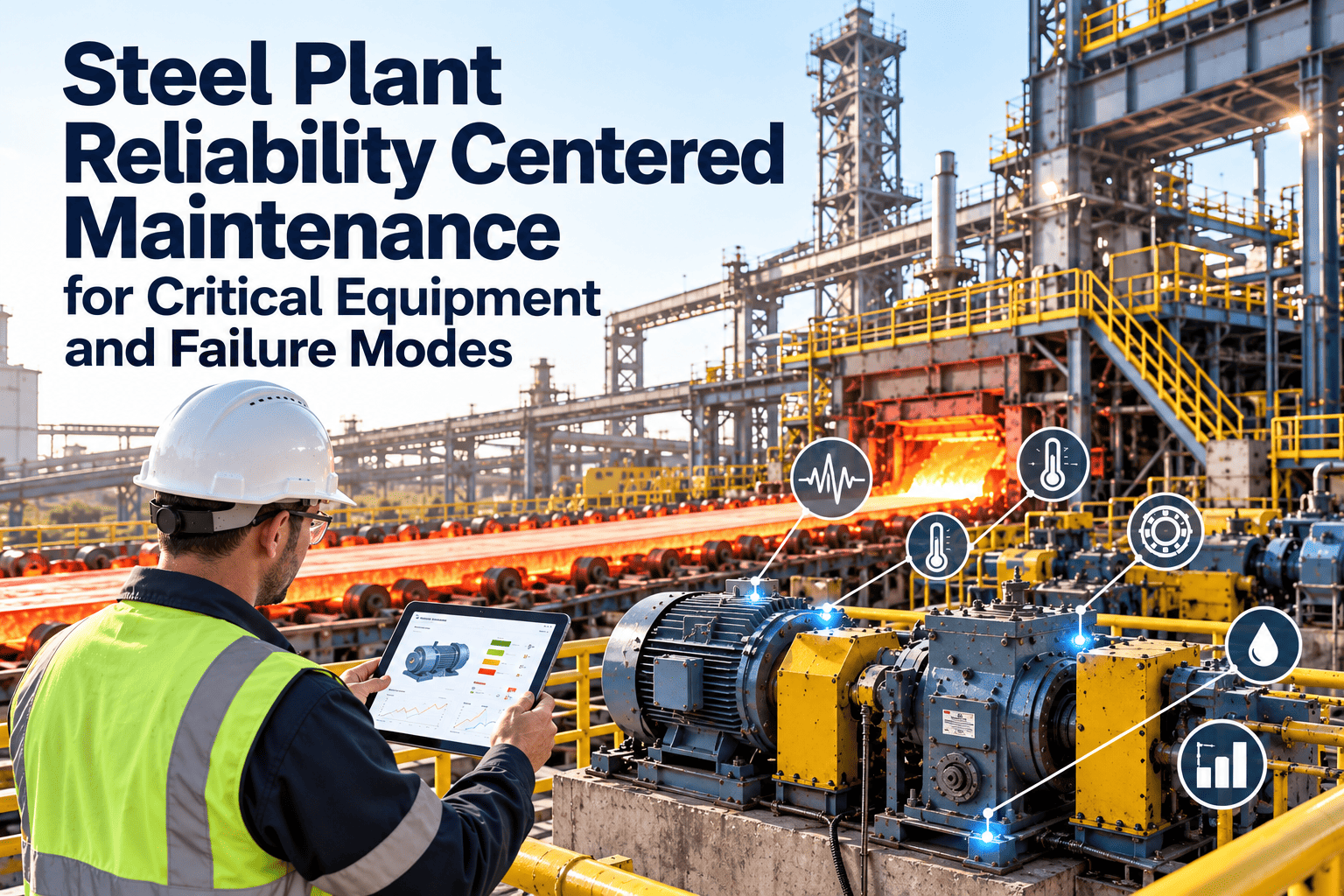
Steel Plant Reliability Centered Maintenance for Critical Equipment and Failure Modes
Build an RCM program that starts with function, ranks failure consequences and ends with tasks your planners can schedule, your technicians can perform and your engineers can review.
Why steel plants need a structured reliability method
Calendar-based preventive plans grow over time without a clear reason for each task. RCM replaces habit with a documented argument for every task.
Heat and thermal cycling
Scale, dust and water
Shock and cyclic loads
Continuous operation
Linked process stages
Step one: rank critical equipment before analyzing anything
RCM is effort-intensive, so use criticality to decide where it is worth the time. Score each asset against the same set of consequence criteria.
Safety
Injury or fatality potentialEnvironment
Emissions, spills, permit limitsProduction
Lost output and bottleneck effectQuality
Defects, downgrades, reworkRepair burden
Cost, lead time, sparesCandidate steel assets and the failures to examine
The list below is illustrative. Your own criticality ranking and failure history decide the final scope.
| Asset group | Primary function | Example functional failures | Example failure modes |
|---|---|---|---|
| Furnace transformer and power systems | Deliver stable power to melting | Loss of power, unstable supply | Insulation degradation, cooling failure, tap changer wear |
| Ladle crane and hoists | Lift and transport liquid steel safely | Cannot lift, cannot hold load | Brake wear, wire rope damage, limit switch fault |
| Caster segments and mold | Guide and support the strand | Misalignment, loss of cooling | Roll wear, bearing failure, nozzle blockage |
| Reheating furnace systems | Heat slabs to rolling temperature | Insufficient heat, no movement | Burner fouling, skid wear, walking beam hydraulics fault |
| Rolling mill main drive and gearbox | Transmit torque at set speed | Cannot transmit, excess vibration | Gear tooth pitting, bearing wear, lubrication starvation |
| Hydraulic and lubrication units | Supply clean fluid at pressure | Low pressure, contaminated fluid | Pump wear, filter blockage, seal leakage |
| Fume extraction fans and filters | Capture and clean process emissions | Reduced airflow, emission excursion | Impeller imbalance, bearing wear, bag failure |
The seven questions behind an RCM analysis
The SAE JA1011 standard describes the criteria a process must meet to be called RCM. Its structure can be read as seven questions asked of each asset.
What are the functions and performance standards?
State what the asset must do, in measurable terms, in its operating context.In what ways can it fail to fulfil them?
List each functional failure, including partial failures such as reduced output.What causes each functional failure?
Identify failure modes at a level where a task can be chosen.What happens when each failure occurs?
Describe warning signs, damage, downtime and any safety or environmental effect.Why does each failure matter?
Classify consequences as hidden, safety, environmental, operational or non-operational.What can be done to predict or prevent it?
Select condition-based, scheduled restoration or scheduled replacement tasks if they are technically sound and worthwhile.What if no suitable task exists?
Choose a default action: failure-finding, redesign or run to failure.
Worked illustration: a rolling mill gearbox
This is an explanatory example, not a plant record. It shows how one function breaks down into failure modes and tasks.
| Functional failure | Failure mode | Effect | Consequence | Task selected |
|---|---|---|---|---|
| Cannot transmit torque | Gear tooth fracture after pitting | Mill stops, gearbox opened for repair | Operational, long repair time | Oil analysis, vibration trend and periodic inspection of tooth surfaces |
| Transmits with excess vibration | Bearing wear | Rising vibration, possible roll mark effects | Operational and quality | Vibration route and bearing temperature check, planned replacement on condition |
| Transmits with excess vibration | Coupling misalignment | Accelerated wear on shaft and bearings | Operational | Alignment check after any mill stand or coupling work |
| Loses lubrication | Pump failure or filter blockage | Overheating and rapid wear | Operational, may cause major damage | Pressure and temperature monitoring, scheduled filter service, standby pump test |
Choosing the right task for each failure mode
Task selection follows logic, not preference. Work down this sequence for each failure mode.
Can the failure be detected early with enough warning?
Is wear predictable with age or use?
Is the function hidden, such as a protective device?
Does a safety or environmental risk remain with no effective task?
Is the consequence low and the repair cheap?
Understanding the P-F interval
Condition-based tasks only work when inspection happens inside the window between detectable degradation and functional failure.
Condition techniques that suit steel plant failure modes
| Technique | Useful for | Example steel plant use |
|---|---|---|
| Vibration analysis | Bearings, gears, imbalance, misalignment | Mill gearboxes, fan bearings, pump sets |
| Oil and grease analysis | Wear, contamination, lubricant condition | Gear oil, hydraulic units, caster roll bearings |
| Infrared thermography | Hot spots in electrical and mechanical parts | Switchgear, motor terminals, furnace cooling circuits |
| Ultrasonic testing | Leaks, thickness loss, bearing lubrication | Compressed air, pipework, bearing condition |
| Motor current and electrical tests | Winding, rotor and supply problems | Large drives, fans, pumps |
| Visual and operator inspection | Leaks, wear, noise, loose parts | Guides, hoses, nozzles, rope condition |
Implementing RCM in six phases
- 1
Select assets
Use criticality ranking, failure history and safety risk to choose the first systems. - 2
Build the team
Include an operator, maintainer, reliability engineer and a facilitator who knows the method. - 3
Analyze functions and failures
Document functions, failure modes, effects and consequences using real history. - 4
Select and approve tasks
Assign task type, interval, craft and duration, and get production and safety sign-off. - 5
Load into the CMMS
Create job plans, schedules, inspection routes and spares lists linked to each failure mode. - 6
Review and improve
Compare work history and failures with the analysis, then update tasks and intervals.
RCM mistakes that weaken the program
Common mistakes
- Starting with every asset in the plant
- Copying generic failure modes with no local history
- Writing tasks that technicians cannot perform in the available window
- Leaving the analysis in a document, outside the CMMS
- Never revisiting intervals after the workshop
Better practice
- Start with a small group of critical systems
- Use failure records, inspection findings and technician knowledge
- Write clear job plans with duration, tools and acceptance criteria
- Link tasks and failure modes to assets and work orders
- Review results on a fixed schedule with failure data
How Oxmaint keeps the RCM program working
RCM produces decisions. Oxmaint maintenance management software gives those decisions a place to run, so tasks are scheduled, results are recorded and feedback is available for the next review.
Structure
- Asset hierarchy with criticality ratings
- Failure codes for modes, causes and remedies
- Spares linked to critical assets
Execution
- Preventive and condition-based schedules
- Mobile inspection routes and checklists
- Work orders with measurements and notes
Learning
- Repeat failure reports by asset and mode
- Compliance and backlog dashboards
- Records to support root cause analysis
Measuring whether RCM is delivering
| KPI | What it indicates |
|---|---|
| Unplanned downtime on critical assets | Whether tasks are catching failures before they interrupt production |
| Mean time between failures by failure mode | Whether specific failure modes are being controlled |
| Share of work found through condition tasks | Maturity of the predictive approach |
| Preventive and inspection compliance | Whether the program is actually being executed |
| Repeat failures after repair | Quality of repairs and root cause actions |
| Spares stockouts on critical assets | Readiness for planned and unplanned work |
| Tasks reviewed or updated each year | Whether the analysis stays current |
Hidden functions: protective devices that nobody notices until they are needed
Steel plants rely on protection systems that stay silent during normal operation. If they fail unnoticed, the next demand can become a serious event.
Safety and process protection
- Emergency stops and interlocks
- Overspeed and overload protection on cranes
- Furnace cooling water flow and temperature alarms
Electrical protection
- Protection relays and trip circuits
- Ground fault detection
- Standby power transfer systems
Environmental protection
- Gas detection and fire suppression
- Emission monitoring and alarm paths
- Spill containment and level alarms
Failure codes that make RCM learn from real work
If work orders close with free text only, the analysis cannot be tested against what actually happened. Structured codes close that gap.
Without structured codes
- Descriptions such as "fixed fan" hide the real cause
- The same failure appears under different wording
- Reliability engineers must read every record by hand
- Failure modes in the analysis cannot be verified
With structured codes
- Problem, cause and remedy recorded on each corrective job
- Repeat failures found by asset, mode and period
- Analysis assumptions checked against actual history
- Root cause studies start from a clear record
Linking RCM tasks to shutdowns and operating windows
Some tasks cannot be done online. RCM should state which tasks need a stop, so planners can place them correctly.
- Tag each task as online, offline or window-dependent when it is approved.
- Group offline tasks by area so one stop covers as many justified tasks as possible.
- Include the spares, permits and crane needs in the job plan, not as a separate note.
- Feed inspection findings back into the next shutdown scope with the failure mode and condition evidence.
- Review deferred tasks with the responsible engineer and record the accepted risk.
Keeping the program alive after the first analysis
- 1
Name an owner
Assign a reliability engineer to each system to maintain the analysis and task list. - 2
Review after events
After a significant failure, check whether the mode was in the analysis and whether the task worked. - 3
Reassess after changes
Modifications, new products or changed duty cycles can alter functions and failure modes.
Questions to settle in the first analysis workshop
Agreeing on boundaries early prevents long debates later and keeps the analysis focused on decisions.
- Where does the system boundary start and end, and which interfaces belong to neighboring systems?
- What operating context applies, including duty cycle, product mix and planned campaign length?
- Which performance standards are measurable, such as pressure, flow, speed or temperature limits?
- What failure history exists in the CMMS, inspection reports and operator logs?
- Who can approve safety-related task changes, and who signs off the final task list?
- How will approved tasks be loaded, scheduled and reviewed after the workshop?