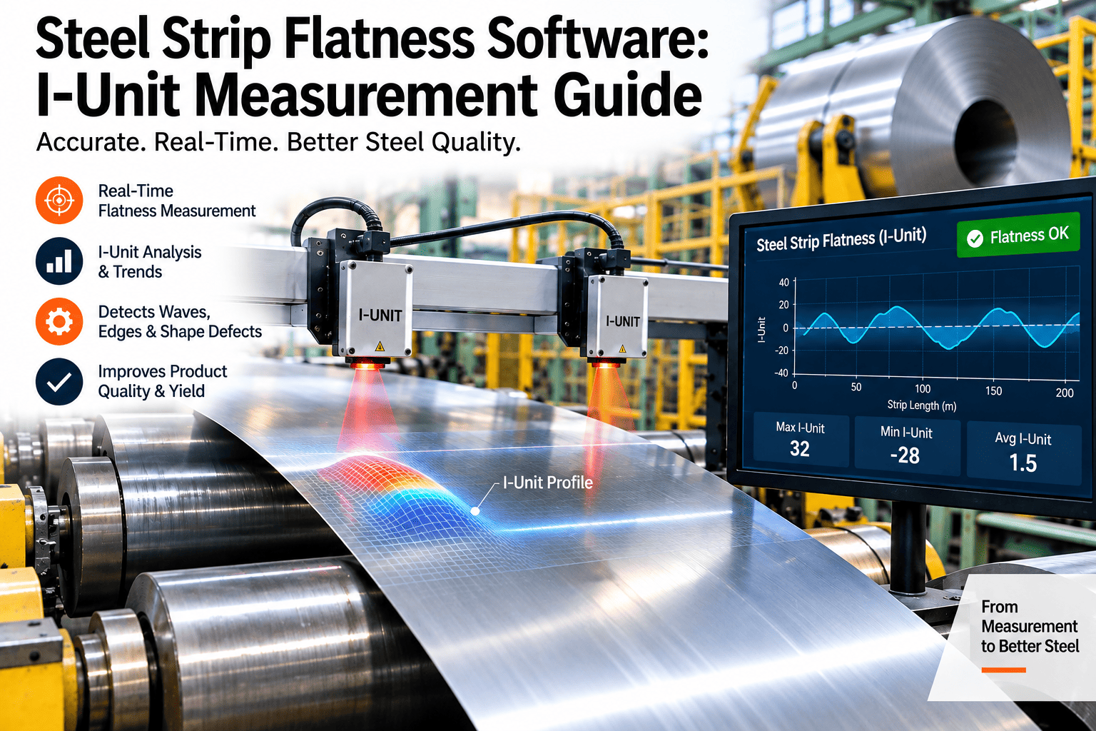
A coil can pass gauge, width, and surface inspection and still be rejected the moment it hits an automotive stamping press or an appliance panel line, because flatness is a defect that only becomes visible once tension is removed. I-units are how the industry quantifies that invisible defect while the strip is still under tension on the mill, and the gap between a shapemeter reading and an actuator's actual response is where most flatness complaints originate. This guide walks through how I-units are measured, what drives edge wave, center buckle, and quarter buckle, the tolerance bands different end-use grades actually specify, and how flatness-focused maintenance software keeps the shapemeter, actuator, and coolant equipment behind that number in a known, trusted state shift after shift.
Flatness is invisible under tension. I-units are how you measure it anyway.
Automotive exposed panels, appliance skin sheet, and precision blanking all specify a maximum I-unit value — and holding it depends on shapemeter accuracy and actuator condition staying in sync, shift after shift.
What an I-unit actually represents
An I-unit expresses the severity of a wave in the strip as the ratio of wave height to wavelength, multiplied by 100 — a dimensionless number that lets a mill compare a long, shallow wave against a short, sharp one on the same scale.
The shapemeter roll sits downstream of the last stand and reads tension variation across dozens of narrow zones spanning the strip width. A zone under lower tension than its neighbors indicates the strip there is longer, relative to width, than the surrounding material — the geometric root of every flatness defect, whether it eventually shows up as edge wave, center buckle, or a localized quarter buckle.
The four wave patterns a shapemeter trace reveals
Edge wave
Repeating waves along one or both strip edges, caused by the edges being rolled relatively longer than the center — often from excess roll crown or edge-drop in the work rolls.
Center buckle
The inverse condition — the strip center is relatively longer than the edges, typically from insufficient roll crown, uneven roll wear, or a thermal crown imbalance across the barrel.
Quarter buckle
A localized wave roughly midway between center and edge, frequently traced to a coolant header zone that is over- or under-cooling a narrow band of the work roll.
Crossbow & coil set
Curvature across the width (crossbow) or along the coil length (coil set) — less an actuator issue than a roll-gap or tension-reel wrap tension symptom carried downstream.
I-unit specifications by end-use grade
Different end uses tolerate very different flatness levels — the same coil that fails an automotive exposed-panel order can still be perfectly acceptable as structural sheet.
| End-Use Grade | Typical I-Unit Limit | Why It's Tight or Loose | Common Failure Driver |
|---|---|---|---|
| Automotive exposed panel | Under 5 IU | Visible under paint gloss at the stamping and assembly stage | Roll crown mismatch, uneven coolant zone response |
| Appliance / coated sheet | 5–15 IU | Visible under coating but less critical than Class A automotive | Actuator response lag, roll wear between changes |
| Commercial / structural | 15–27 IU | Formed or fabricated further downstream, less visually critical | General roll wear, tension reel wrap variation |
| Rejection threshold | Above 27 IU | Industry-standard ceiling before the coil is unsellable as flat product | Compounding, uncorrected actuator or roll condition drift |
From shapemeter reading to actuator correction
Flatness control is a closed loop: the shapemeter reads a deviation, the mill's shape control system calculates a correction, and an actuator applies it — and each stage of that loop is a piece of equipment with its own maintenance requirement.
Shapemeter roll sensing zones
Individual load-cell or fiber-optic sensing segments across the roll width must stay calibrated to each other — a single drifted zone reads as a false flatness defect and can trigger an unnecessary correction elsewhere on the strip.
Work roll bending actuators
Hydraulic roll-bending cylinders adjust the effective crown of the work roll in real time. Seal wear or a sluggish servo valve slows the correction response, letting a wave persist longer than the control system intends.
Roll shifting (CVC) systems
Continuously variable crown systems shift work rolls axially to change the effective crown profile — a worn shifting rail or a positioning sensor out of tolerance produces a repeatable, hard-to-diagnose shape defect.
Coolant header zone control
Zone-specific coolant valves manage thermal crown across the roll barrel. A partially blocked nozzle or a stuck valve creates a localized hot or cold band that shows up directly as a quarter-buckle pattern.
Load-cell vs. fiber-optic shapemeter rolls
Not every shapemeter roll measures the same way, and the maintenance profile of each technology is different enough that it changes what a plant should be inspecting for.
Segmented load-cell rolls
The traditional approach: individual load-cell segments under the roll surface measure tension zone by zone. Mechanically robust, but each cell can drift independently and needs periodic zero-offset verification.
Fiber Bragg grating (FBG) rolls
Newer optical shapemeter rolls use fiber-optic strain sensing for finer spatial resolution — often down to a few millimeters across the width — but depend on the fiber and connector staying free of contamination and mechanical damage.
Whichever technology a mill runs, the underlying maintenance question is the same: does every zone across the roll width still read tension accurately relative to its neighbors, and would an operator actually notice if it did not? A shapemeter that has not been zero-checked since its last work roll change is a common, quiet source of shape data that looks plausible on the trend screen but no longer reflects the strip actually leaving the stand.
What a shape-loop verification should cover at shift start
A short, structured check at the start of each shift catches most shape-loop drift before it reaches a full coil of out-of-spec product.
Shapemeter zero-offset check
Confirm zone-to-zone readings against a known reference before the first coil of the shift runs through the last stand.
Bending actuator response test
A quick step-response check on the roll-bending cylinders confirms the correction loop is still reacting within its calibrated time window.
Coolant header flow verification
Zone flow rates are checked against baseline to catch a partially blocked nozzle before it produces a quarter-buckle pattern on a live order.
First-coil I-unit review
The first coil of the shift is reviewed against the grade's I-unit spec before the run continues at full schedule, catching any drift the earlier checks missed.
A 6 I-unit drift that cost a full automotive lot
Consider a tandem cold mill running several stands and supplying exposed-panel coil under a strict 5 IU specification for a major automotive customer. A roll-bending servo valve on the fourth stand began responding roughly 15% slower than its calibrated baseline — not enough to trip an alarm, but enough to blunt the correction on fast-changing edge wave.
The cost of that missed lot was not just the rejected coils — it included the line-down time at the customer's stamping plant, the expedited replacement order, and the internal investigation to confirm the root cause before the next shipment could be released. A response-time trend that had been checked at shift start would have flagged the same degradation as a maintenance item, not a customer complaint.
I-unit discipline across end-use segments
Class A exposed surfaces
Doors, hoods, and fenders are viewed at a glancing angle under showroom lighting, where even a 5–6 IU wave is visible as an "oil can" effect after painting and assembly.
Coated and painted panels
Refrigerator doors and range panels sit at a wider I-unit tolerance than automotive Class A, but coil-to-coil consistency still matters for a customer running a continuous paint line.
Stamped and formed components
Flatness deviation entering a progressive die can shift blank positioning and increase die wear, making I-unit consistency a tooling-life issue as much as a cosmetic one.
Connect actuator health to your flatness spec — before the next automotive coil ships.
See how cold rolling teams track shapemeter, bending, shifting, and coolant zone condition against their I-unit performance.
How Oxmaint keeps the flatness control loop trustworthy
Oxmaint does not replace the mill's shape control system — it manages the condition of the sensing and actuation equipment that system depends on, and links that condition history to coil-level flatness performance.
Shape control asset hierarchy
Shapemeter roll, bending actuators, shifting systems, and coolant zone valves are modeled as linked assets under each stand, so a correlated failure pattern is visible across the loop.
Actuator response-time PM triggers
Bending cylinder seals, servo valves, and shifting rail wear are scheduled against response-time and cycle-count thresholds, not just calendar intervals.
Shapemeter calibration checklists
Zone-by-zone calibration checks are logged on a mobile form, with drift on any individual sensing segment flagged before it produces a false correction trigger.
Deviation-to-repair routing
A flagged actuator response lag or a blocked coolant nozzle generates a corrective work order automatically, routed before the next grade change.
Critical spares for the shape loop
Servo valves, load-cell segments, and coolant nozzles are tracked against consumption, so a required repair is never delayed by a part that should have been on the shelf.
Coil-level flatness traceability
Actuator and sensor maintenance history is retained against the production lot, giving quality teams a defensible link when a customer flatness complaint needs root-cause review.
Reactive coil-by-coil response vs. a connected shape-loop record
- Flatness rejects are handled one coil at a time, with no trend view
- Actuator maintenance is scheduled by calendar, disconnected from performance data
- Root-cause review after a customer complaint means manually pulling shapemeter logs
- A slowly degrading servo valve runs until it fails outright
- Flatness deviations roll up by stand, actuator, and grade for trend visibility
- PM triggers combine response-time and cycle-count thresholds with condition data
- Root-cause review is a query against a linked asset and production record
- Gradual actuator degradation is flagged before it reaches a customer-visible IU deviation
Strip flatness and I-unit measurement — answered
Why does flatness only show up once tension is released?
Under coiling or rolling tension, length differences across the strip width are held flat by that tension. Once the strip is uncoiled or blanked without tension, those hidden length differences reappear as visible waves.
Can a shapemeter itself be the source of a false flatness reading?
Yes — an individual sensing zone that has drifted out of calibration produces a reading that does not match the strip's actual shape, which can trigger an unnecessary or incorrect actuator correction elsewhere across the width and, in some cases, introduce a new defect while trying to fix one that was never really there.
How is center buckle different from quarter buckle in root cause?
Center buckle usually traces to overall roll crown or global thermal crown imbalance, while quarter buckle is typically localized to a single coolant zone or a narrow section of actuator response — different equipment, different fix.
Does Oxmaint replace our mill's automatic flatness control system?
No — Oxmaint manages the maintenance and calibration condition of the sensing and actuation equipment that control system depends on. Schedule a Demo to see how it fits alongside your existing mill automation.
How fast can a cold mill get its shape-loop assets tracked?
Most mills have shapemeter, bending, shifting, and coolant zone assets modeled and on a PM schedule within two to three weeks. Get Started to begin your setup.
Keep the shapemeter, actuators, and coolant zones behind your I-unit spec in a known state
Cold rolling teams supplying automotive and appliance grades use Oxmaint to connect shape-loop equipment condition to flatness performance — not a coil-by-coil guess.
Free trial · No credit card