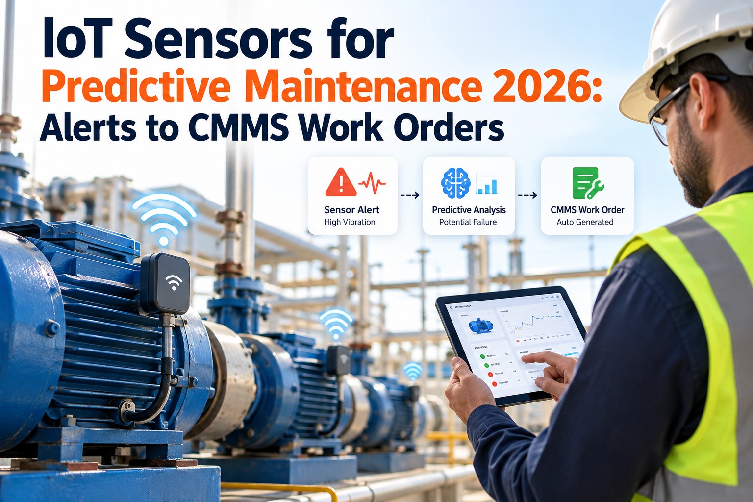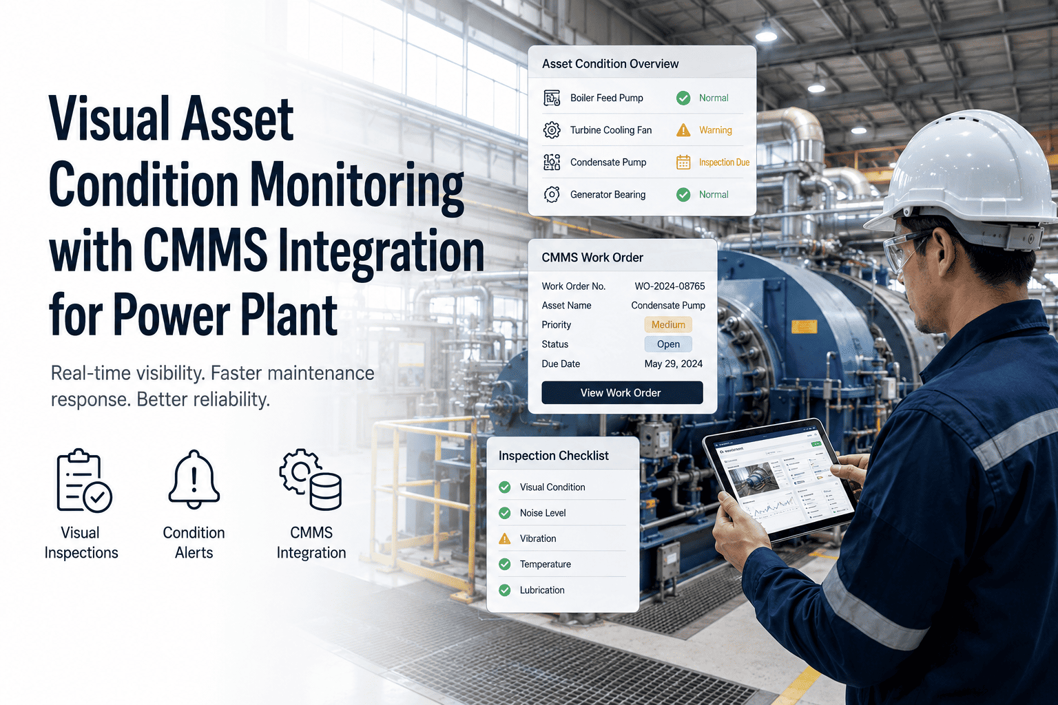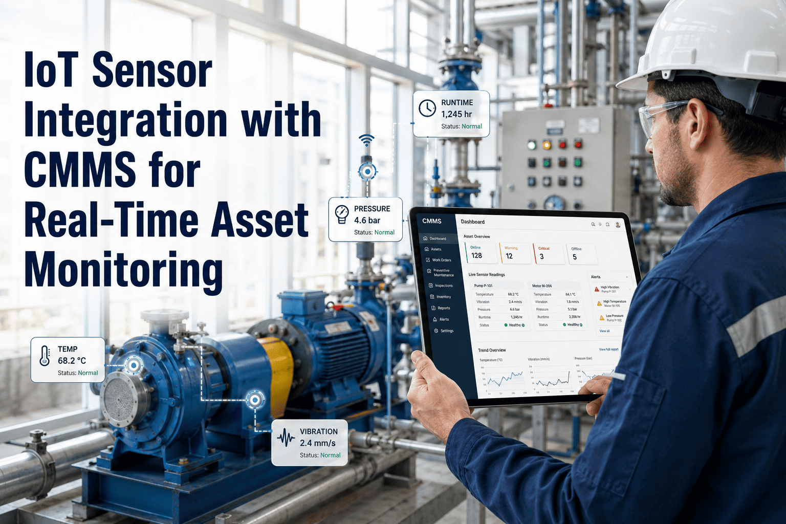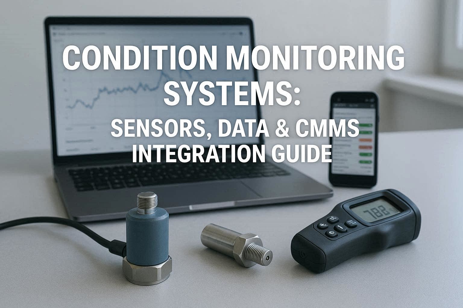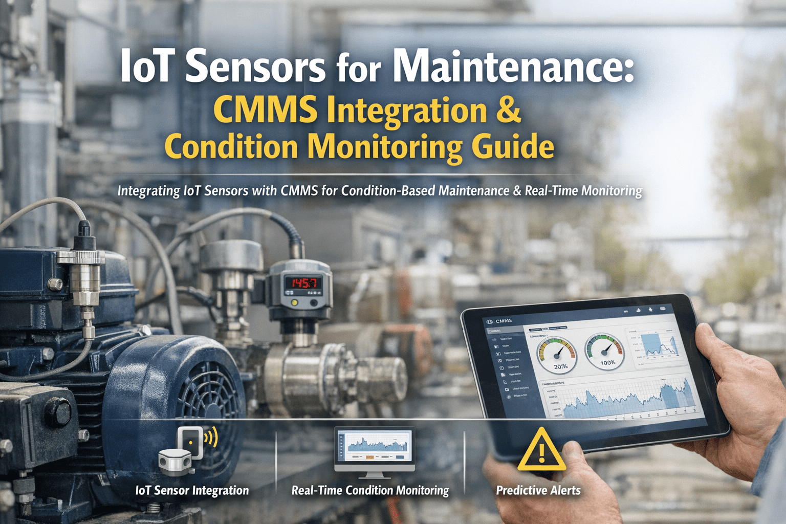
Most maintenance teams do not have a data problem — they have a data-action gap. Your equipment is already generating thousands of signals every hour: temperature rises before a bearing seizes, vibration patterns shift weeks before a gearbox fails, pressure drops before a pump cavitates. The problem is that none of those signals reach the person who could act on them in time to prevent the failure. IoT sensors connected to a CMMS close that gap — transforming equipment telemetry into timestamped work orders, automatically, before the breakdown happens. Sign up for Oxmaint to connect your first sensor and create your first condition-based alert in under an hour.
The IoT-to-CMMS Data Flow: From Equipment Signal to Resolved Work Order
Every IoT maintenance program follows the same fundamental loop. Sensors capture equipment condition. Data transmits to the CMMS. The CMMS applies your alert rules. A work order is created, assigned, and resolved. That loop — when configured correctly — runs 24 hours a day without human monitoring. Sign up for Oxmaint to build your first sensor-to-work-order loop today.
Core IoT Sensor Categories for Industrial Condition Monitoring
Each maintenance failure mode requires the sensor type best suited to detect its early signature. Choosing the right sensor for the right asset — and knowing what threshold to alert on — is the foundation of an effective IoT maintenance program. Book a demo to map your critical assets to the right sensor types in Oxmaint.
Tri-axial accelerometers detect bearing wear, shaft imbalance, misalignment, and resonance in rotating machinery. Vibration monitoring is the single highest-value sensor type for industrial maintenance — most rotating equipment failures produce detectable vibration signatures 3–8 weeks before audible symptoms appear. Mounted on motor housings, gearboxes, pump casings, and compressor frames.
- Bearing inner/outer race defect frequencies
- Gear mesh anomalies and tooth damage
- Shaft imbalance and coupling misalignment
Contact and non-contact temperature monitoring on motor windings, bearing housings, electrical cabinets, heat exchangers, and refractory surfaces. Temperature delta-T analysis — comparing inlet versus outlet on cooling systems — identifies restriction, fouling, and flow degradation before equipment overheats. IR pyrometers enable monitoring in environments where contact sensors cannot survive.
- Motor winding overheating from insulation degradation
- Cooling circuit restriction via delta-T rise
- Electrical hotspots indicating loose connections
Differential and absolute pressure monitoring on hydraulic systems, compressed air networks, pump discharge lines, and filter housings. Pressure drop across a filter signals blockage before flow restriction affects process quality. Rate-of-pressure-drop analysis in hydraulic circuits identifies leak trajectories before systems fail completely. Pump cavitation produces characteristic pressure fluctuation patterns detectable weeks before mechanical damage.
- Hydraulic system leak rate trajectory
- Filter and strainer blockage before flow impact
- Pump cavitation onset detection
Current transformers clamped non-invasively on motor supply cables perform Motor Current Signature Analysis (MCSA) — detecting broken rotor bars, winding insulation degradation, phase imbalance, and bearing faults through current spectrum analysis without requiring physical sensor contact on the motor. Power quality monitoring identifies harmonic distortion from variable frequency drives that accelerates motor and drive component wear.
- Broken rotor bar detection via sideband analysis
- Phase imbalance causing uneven thermal stress
- Harmonic distortion from VFD degradation
Inline oil quality sensors installed in gearbox and hydraulic lube circuits continuously monitor viscosity, ferrous particle count, water ingress, and oxidation state. Eliminating scheduled oil changes in favor of condition-based oil changes alone recovers significant maintenance cost — most scheduled changes occur when oil still has substantial remaining life. Ferrous particle count trending provides 3–6 weeks advance warning of gear wear before vibration signatures appear.
- Gear wear particle accumulation trend
- Water ingress contaminating lubricant
- Oil oxidation requiring condition-based change
Airborne ultrasonic detectors identify compressed air and steam leaks — a major hidden energy cost in industrial facilities where leakage can account for 20–40% of compressed air generation. Contact ultrasonic sensors on piping, pressure vessels, and storage tanks track wall thickness changes over time for corrosion-under-insulation detection without removing lagging. Both applications generate CMMS work orders automatically when leak signatures or thinning rates exceed configured limits.
- Compressed air leak location and sizing
- Steam trap failure — passing or blocked
- Wall thinning rate on pressure vessels
Manual Inspection Rounds vs. IoT Condition Monitoring
Manual inspection walks have been the backbone of industrial maintenance for decades. IoT condition monitoring does not eliminate them — it fills the gaps between them with continuous equipment surveillance that no human inspection schedule can match.
| Monitoring Capability | Manual Rounds | IoT + Oxmaint CMMS |
|---|---|---|
| Coverage frequency | Every 4–8 hours | Continuous — every second |
| Bearing fault detection | Audible stage only | 3–8 weeks pre-failure |
| Data consistency | Variable by inspector | Objective and repeatable |
| Trend analysis | Point-in-time only | Continuous with rate-of-change |
| Work order creation | Manual — hours delay | Automatic — seconds delay |
| Night shift quality | Often reduced | Identical to day shift |
Swipe to see full comparison
IoT Sensor Integration Checklist: From First Sensor to Full Condition Monitoring
Use this checklist to audit your current IoT integration readiness and identify the gaps blocking you from condition-based maintenance. Each section is expandable and contains actionable verification steps. Sign up for Oxmaint to start tracking progress against this checklist in a live CMMS.
Before deploying a single sensor, rank your assets by failure consequence and select sensor types matched to the dominant failure mode. Deploying vibration sensors on low-criticality assets while ignoring high-criticality hydraulic systems is the most common IoT implementation mistake.
The network layer is where most IoT projects stall. Edge gateways must be positioned for coverage, secured against cyber threats, and configured to forward normalized data to the CMMS without manual intervention.
Alert thresholds set before baseline data is collected generate excessive false positives — the fastest way to lose maintenance team trust in the system. Run 2–4 weeks of data collection before activating work order generation rules.
Sensor data that generates alerts but no work orders delivers no maintenance value. The integration between condition alert and CMMS work order must be seamless, automatic, and structured to include the information technicians need to act immediately. Sign up for Oxmaint to configure your work order templates for sensor-triggered alerts.
An IoT condition monitoring program that was well-calibrated at launch will drift if alert rules are never reviewed. Monthly refinement cycles using actual work order outcomes dramatically improve signal quality over time. Book a demo to see Oxmaint's alert performance analytics.
Your Equipment Is Already Signaling Failures. Your CMMS Just Isn't Listening.
Oxmaint connects your IoT sensors — vibration, temperature, pressure, current — to automated work orders that reach the right technician before the failure reaches your production line. No spreadsheets. No missed alerts. No 3am emergency calls.
Choosing the Right IoT Communication Protocol for Industrial Maintenance
Protocol selection determines sensor range, power consumption, latency, and cybersecurity posture. Match the protocol to the environment — not the other way around. All four major industrial IoT protocols are supported natively by Oxmaint's edge gateway layer.
Lightweight publish-subscribe protocol over TCP/IP. Industry standard for IIoT sensor-to-cloud data transmission. Supports QoS levels 0–2 for guaranteed delivery of critical condition alerts.
- High-frequency vibration data streams
- Edge gateway to cloud transmission
- Reliable delivery of critical alerts
Industrial interoperability standard with built-in security model. Native integration with Siemens, ABB, Rockwell, and most major SCADA/PLC platforms. Best choice for connecting existing plant automation to IoT data flows.
- SCADA historian integration
- PLC tag subscription
- MES production data bridging
Self-organizing mesh network for process instrumentation. Battery-powered sensors with 2–5 year battery life. Designed for hazardous area classifications — intrinsically safe options available for ATEX/IECEx zones.
- Hazardous area temperature sensors
- Remote or inaccessible asset monitoring
- Retrofit on existing HART instruments
Ultra-low power protocol for sensors requiring long battery life over large facility areas. Ideal for outdoor tank farms, pipeline monitoring, and geographically dispersed equipment where running wired infrastructure is impractical.
- Outdoor tank and pipeline monitoring
- Multi-building campus deployments
- 10+ year battery life applications
We spent three years trying to build predictive maintenance with a dashboard and manual inspection rounds. It never worked — the dashboard showed the data, but nobody acted on it fast enough. When we switched to connecting our vibration sensors directly to Oxmaint's work order engine, the response time went from hours to minutes. In the first six months, we caught four bearing failures before they became production stoppages. The payback on the entire sensor deployment came before month four.
IoT Sensor Integration & Condition Monitoring — Common Questions
No. Retrofit wireless sensors clamp, bolt, or magnetically attach to existing equipment without modification. A tri-axial vibration sensor mounts on a motor housing in under 10 minutes. Temperature clamps go on pipe surfaces without pipe cutting. Current transformers clip onto cable bundles without electrical isolation. IoT condition monitoring works equally well on equipment that is 5 years old or 30 years old — the equipment's age does not determine whether useful condition signals are available. Sign up for Oxmaint to map your existing assets to compatible sensor types.
A meaningful first phase typically covers 20–40 sensors on the 8–15 most critical assets in the facility. This provides enough coverage to prevent the highest-consequence failures while keeping initial investment manageable. The business case for expanding to 80–200 sensors is almost always established by the first-phase results — documented prevented failures and their cost provide the internal justification for expansion. Start narrow and data-rich rather than broad and shallow.
Condition-based maintenance (CBM) triggers maintenance actions when measured condition parameters cross defined thresholds — regardless of whether failure is predicted. Predictive maintenance uses historical condition data and machine learning models to forecast the remaining useful life and schedule intervention at the optimal time before failure. In practice, most IoT maintenance programs start with condition-based thresholds (simpler, faster to implement) and evolve toward predictive models as failure history accumulates. Oxmaint supports both approaches from a single platform, allowing you to start with threshold rules and layer in predictive analytics as your data matures. Book a demo to see both approaches configured side by side.
Oxmaint's sensor integration layer performs edge aggregation — computing summary statistics (RMS, peak, crest factor, frequency band power) at the gateway before sending to the CMMS. Raw high-frequency data stays at the edge for trend analysis; only actionable condition indicators reach the work order engine. Combined with configurable persistence rules (alert must persist for a defined duration before creating a work order) and deduplication logic, the system converts thousands of daily sensor readings into a manageable number of meaningful maintenance tasks.
The primary risk is creating a pathway from the internet to the OT network via the sensor data channel. Oxmaint's architecture mitigates this by positioning the edge gateway in the plant DMZ — never on the OT network directly — and using one-directional data flow from sensor to cloud. No inbound connections from Oxmaint's cloud ever reach the plant network. All transmissions use TLS 1.3 with certificate authentication. The CMMS layer (IT) and the sensor/SCADA layer (OT) remain architecturally separated. Sign up and our integration team will walk through your network security requirements in the first onboarding session.
Connect Your First Sensor. Create Your First Condition Alert. Prevent Your First Failure.
The gap between equipment failure signals and maintenance action costs industrial facilities billions every year. Oxmaint closes that gap — connecting IoT sensors, condition thresholds, and CMMS work orders into a single automated loop that runs 24 hours a day without a human in the middle.