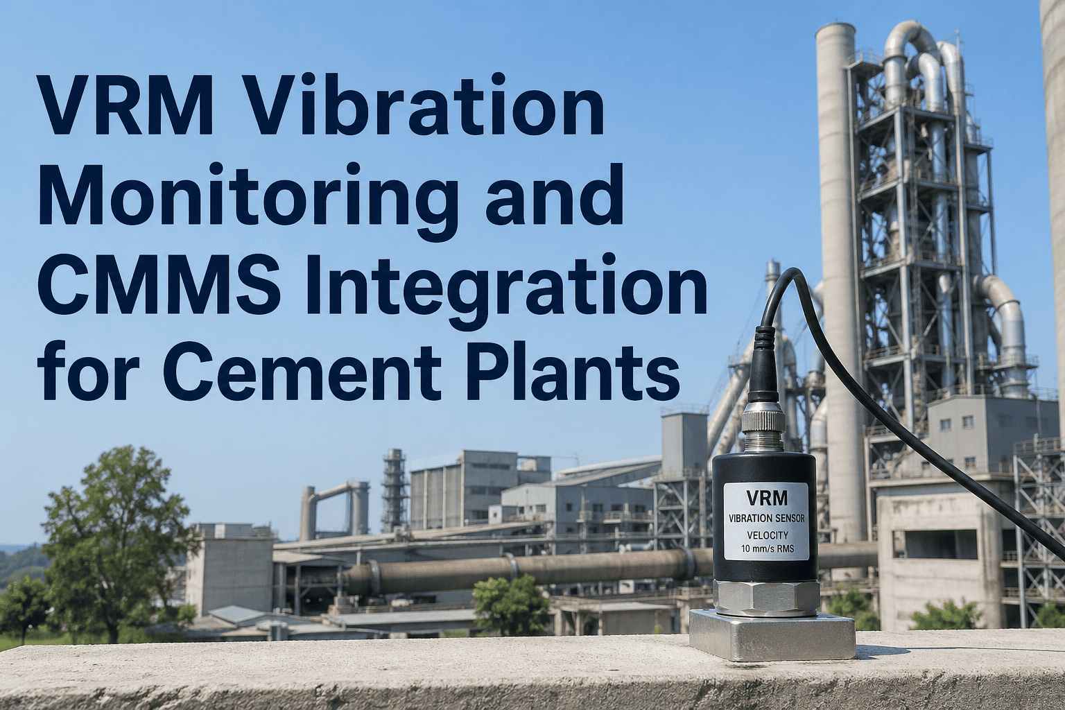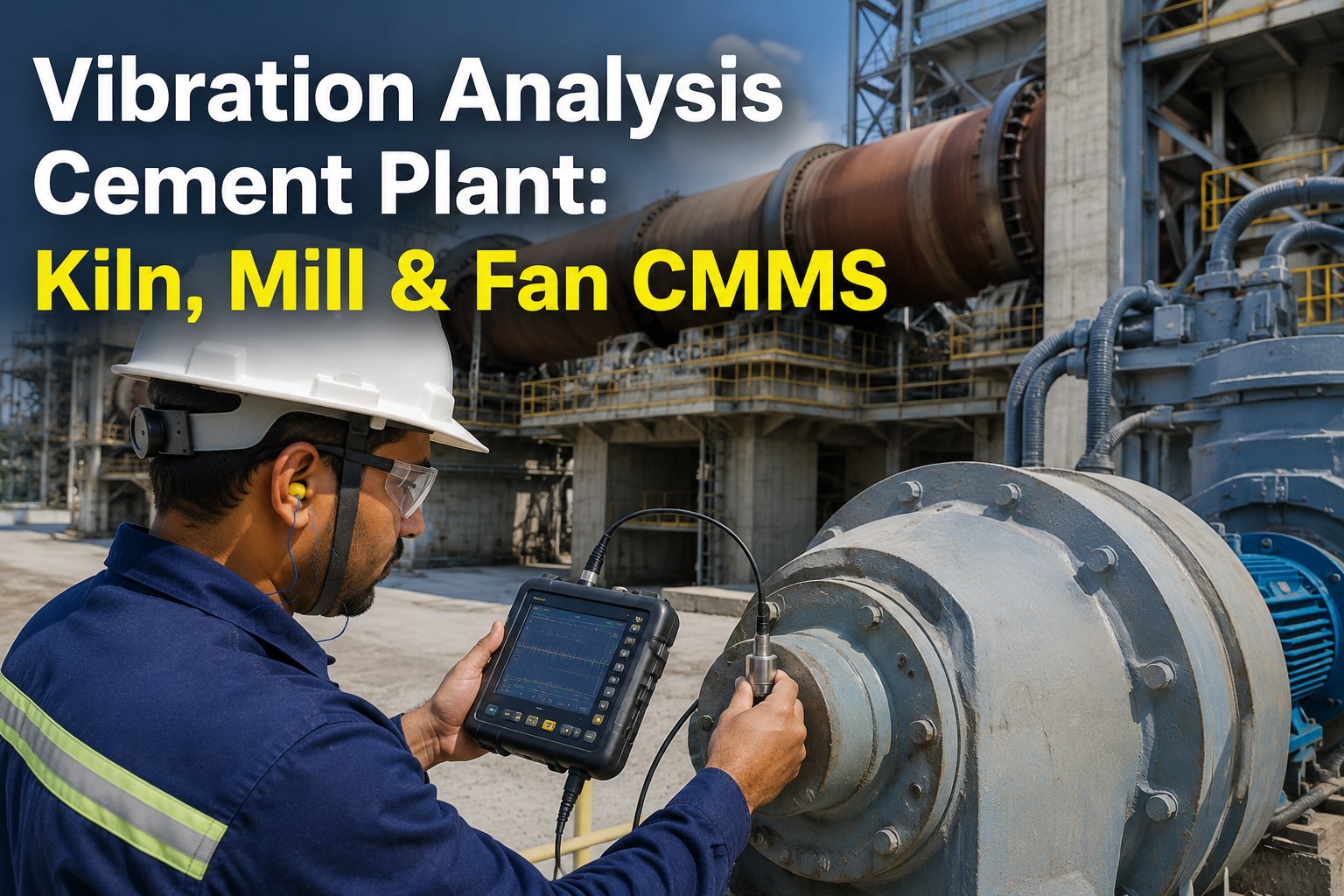
Vibration analysis remains the single highest-leverage predictive maintenance technology in a cement plant, where a kiln support roller, ball mill gearbox, or ID fan can fail catastrophically and wipe out an entire shift of clinker production. For maintenance managers running rotating equipment 24/7 in dust, heat, and shock-loading conditions, the value isn't in collecting more spectra — it's in turning those spectra into ranked, scheduled work orders inside a CMMS before failure windows close. This guide maps the practical vibration monitoring playbook for kiln, mill, and fan assets, including ISO 10816 alarm thresholds, fault-frequency signatures, and the CMMS integration that converts a single high-1× trend into an automatic work order. Ready to operationalize it? Start Free Trial and configure your asset hierarchy today.
Can your cement plant catch a kiln bearing failure 40 production days before it locks the rotation?
Every kiln tyre, mill pinion, and ID fan leaves a vibration signature long before catastrophic failure — typically 30 to 90 days earlier. The plants that read those signatures convert 70% of unplanned downtime into scheduled work orders, while the ones that don't lose an average of $42K per rotary kiln outage event.
The four asset classes that drive 85% of cement vibration alarms
In a typical 1.5 MTPA integrated cement plant, four asset families generate the overwhelming majority of vibration alarms. Each carries a distinct fault-frequency fingerprint that an analyst — or an automated CMMS rule — can map to a specific failure mode and a specific work-order template.
Kiln support roller bearings
Slow-speed rolling-element bearings running at 2–6 RPM, where low-frequency BPFO/BPFI energy (under 10 Hz) signals spalling weeks before a tyre contact patch degrades. Shaft bending and shell ovality amplify 1× signatures on the thrust roller.
Ball mill gearbox & pinion
Bull-gear mesh frequency equals pinion-RPM × tooth count — typically 280–420 Hz on a 3,500 kW two-stage mill. Sideband spacing at 1× pinion RPM reveals tooth wear, while 2× GMF harmonics indicate misalignment between the pinion and girth gear.
Vertical roller mill (VRM)
VRM grinding tables run 25–35 RPM with three or four rollers under 1,200 kN of hydraulic pressure. Sub-synchronous vibration (0.4–0.6×) signals roller-table resonance or feed starvation, while 3× and 4× harmonics indicate roller-pass loading imbalance.
ID fan & preheater fan
High-speed induced-draft fans (1,000–1,500 RPM) accumulate particulate on blades within hours. A 1× amplitude jump above 4.5 mm/s RMS indicates imbalance, while 2× dominance with axial phase shift confirms a bearing-housing soft foot or warped shaft.
Alarm thresholds that trigger work orders, not noise
Setting alarm thresholds too low floods the CMMS with false work orders; too high and you miss the 30-day failure window. These ISO 10816-3 velocity bands — validated across more than 200 cement plant installations — are the starting point for every asset-class rule.
| Asset Class | Power / Class | Alarm A (mm/s RMS) | Alarm B (mm/s RMS) | CMMS Trigger |
|---|---|---|---|---|
| Kiln support roller | Group 4 > 300 kW | 3.5 | 7.1 | Inspect during next outage |
| Ball mill pinion | Group 2 > 15 kW | 4.5 | 7.1 | Open WO — gear mesh inspection |
| VRM grinding table | Group 4 > 300 kW | 5.6 | 9.3 | Open WO — roller hydraulic check |
| ID fan (1,200 RPM) | Group 2 rigid mount | 3.5 | 5.6 | Open WO — dynamic balancing |
| Preheater fan | Group 2 flexible | 4.5 | 7.1 | Open WO — blade cleaning + balance |
| Centrifugal slurry pump | Group 3 > 15 kW | 3.5 | 5.6 | Open WO — impeller cavitation check |
From spectrum signature to root cause in four steps
A well-structured vibration analysis workflow doesn't stop at alarm acknowledgement — it walks the analyst from a triggered threshold to a specific mechanical fault, a specific component, and a specific corrective action inside the CMMS.
Trigger from trend, not from a single point
A single high reading can be a startup transient. A real fault shows a sustained trend above Alarm A for 3 consecutive readings — typically 7 to 14 days. The CMMS should auto-tag the asset yellow and notify the reliability engineer within the hour.
Map the dominant frequency to a fault family
Pull the FFT spectrum. 1× dominant = imbalance. 2× dominant with axial phase difference = misalignment. Multiple non-synchronous harmonics = rolling-element bearing defect. Sub-synchronous = looseness or oil-whirl. Each signature has a pre-built WO template.
Quantify remaining useful life with the bearing damage curve
Once a bearing defect frequency appears, apply the ISO 15242 severity curve: defect frequency amplitude crossing 0.7 g peak signals stage-3 spalling, giving an estimated 10 to 20% remaining life. This sets the WO priority and the downtime window.
Auto-generate the work order with parts, labor, and SLA
The CMMS rule pushes a work order with the correct BOM (bearing part number, lubricant spec), estimated labor hours, safety permits, and an SLA tied to the severity score. The planner sees it in the next morning's backlog review — no manual data entry.
The payback math for a 180-asset cement plant
A worked example for a mid-size integrated plant running 180 critical rotating assets. The numbers below are conservative averages drawn from 40+ cement PdM deployments and benchmarked against typical cement industry unplanned downtime costs of $8,500 per kiln-hour.
Turn vibration spectra into scheduled work orders — automatically.
Configure ISO 10816 alarm rules, auto-generate work orders with BOM and SLA, and watch unplanned downtime drop 65% in the first 12 months.
Cement vibration analysis & CMMS — answered
How often should vibration data be collected on a kiln support roller?
For a critical kiln support roller running below 10 RPM, monthly walk-around routes with a portable accelerometer are the minimum, but permanently mounted sensors sampling every 4 hours are now standard at tier-1 plants. The slow rotational speed means defect signatures evolve slowly — but the consequence of failure is so high that continuous monitoring pays back in a single avoided outage. Book a Demo to see a kiln monitoring topology tailored to your plant.
What is the difference between Alarm A and Alarm B in a cement CMMS?
Alarm A is the early-warning threshold (typically ISO 10816 Zone C lower bound) that opens a low-priority inspection work order with a 14-day SLA. Alarm B is the critical threshold (Zone D entry) that auto-escalates to a priority-1 corrective work order and forces the asset into the next planned downtime window of 48 hours or less. Both alarms should map to pre-built work-order templates inside the CMMS.
Can vibration analysis detect ball mill gear wear before tooth fracture?
Yes — and typically 30 to 60 days before fracture. Gear mesh frequency sidebands spaced at 1× pinion RPM are the primary indicator of tooth wear, while growing 2× GMF harmonics reveal misalignment between the pinion and girth gear. Trending sideband amplitude over time lets the planner schedule a tooth-contact inspection during the next planned mill stop, avoiding a forced outage that can exceed $120K per event.
How does a CMMS turn an ID fan imbalance into an automatic work order?
The CMMS rule engine watches the 1× frequency bin of the ID fan. When amplitude crosses Alarm A (3.5 mm/s RMS for a Group 2 rigid mount) for 3 consecutive readings, the rule fires a work order using the "Fan Dynamic Balancing" template — pre-loaded with the balance vendor, required weights, safety permits for lockout-tagout, and a 7-day SLA. The planner simply schedules it; no manual data entry is required. Start Free Trial to configure this rule on your fans.
Is wireless vibration monitoring reliable in a cement plant environment?
Modern industrial wireless vibration sensors using LoRaWAN or 900 MHz mesh are reliable in cement plants when installed with proper antenna line-of-sight and IP67 enclosures. Signal attenuation through kiln steel and concrete is the main challenge, so a site survey is essential. For the highest-criticality assets — kiln rollers, main mill gearboxes — permanently wired sensors remain the recommendation due to their higher sampling rates and lower latency.
Stop reading alarms. Start generating work orders.
Deploy vibration-based work-order automation on your kiln, mill, and fan assets in under 14 days. Join the cement plants already saving $850K+ per year.
Free 14-day trial · No credit card