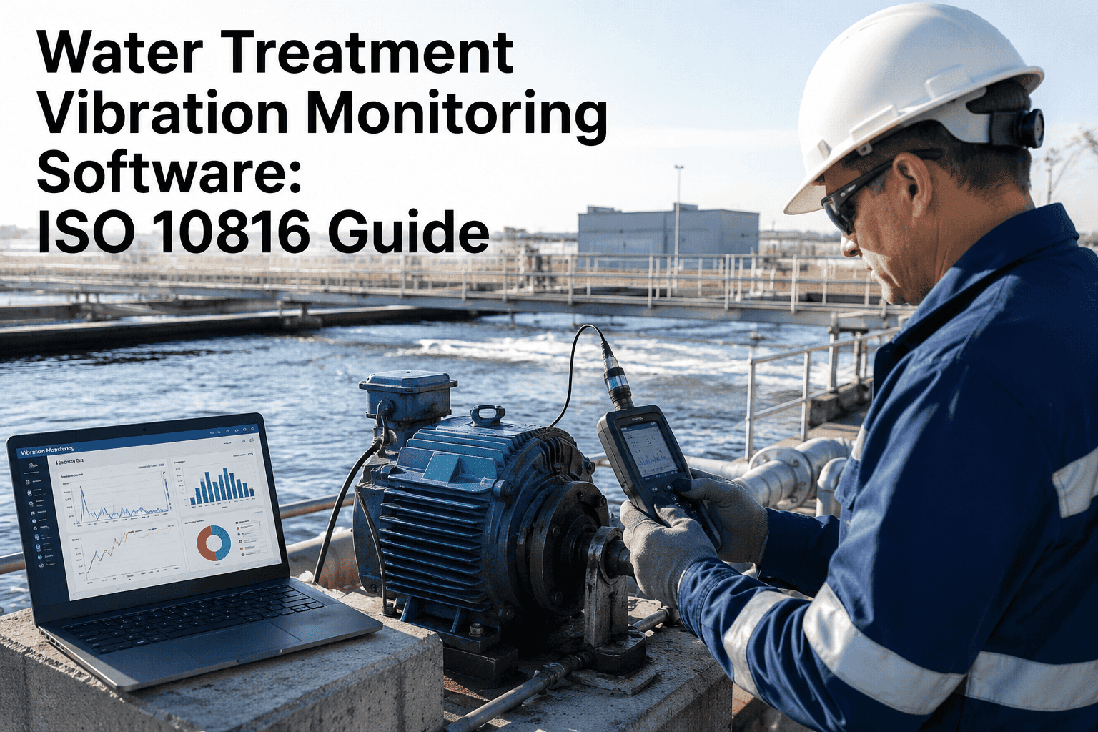
A pump bearing failing at a water treatment plant rarely announces itself with a bang — it whispers first, in vibration amplitudes that climb slowly across weeks before the motor housing gets hot enough for anyone to notice by hand. ISO 10816 is the international standard that turns that whisper into a number, classifying every pump, motor, and blower into vibration severity zones from A through D so operators know exactly when a reading means nothing and when it means shut the unit down. Utilities running continuous vibration monitoring against ISO 10816 zones catch bearing wear and impeller imbalance weeks before failure, instead of discovering it during an emergency callout that risks a sanitary sewer overflow and the regulatory fines that follow. Start free with Oxmaint to put your pump fleet on live ISO 10816 monitoring today.
The ISO 10816 Zone Ladder
ISO 10816-3 classifies vibration severity into four zones based on RMS velocity in mm/s, adjusted for machine group and mounting type. Every pump, motor, and blower in a treatment plant can be scored against this ladder in real time — the same ladder reliability engineers everywhere use to decide whether a reading is nothing, a note-worthy trend, or a shutdown decision. What makes the standard powerful is not just the numbers themselves but the consistency it brings: two engineers at two different utilities reading the same vibration data will reach the same conclusion about severity, because the zone boundaries are not a matter of local judgment.
A
Up to 1.12 mm/s
New or reconditioned
Typical of newly commissioned or recently overhauled machines. This is the baseline condition every unit should return to after major maintenance.
B
Up to 2.8 mm/s
Acceptable long-term
Normal operating range for unrestricted long-term running. The ALERT threshold typically sits at this zone's upper boundary.
C
Up to 7.1 mm/s
Investigate now
Short-term operation is acceptable but corrective maintenance should be scheduled. Continued running at this level accelerates wear.
D
Above 7.1 mm/s
Damage occurring
Vibration at this level is causing active damage to bearings and other components. The unit should be taken out of service immediately.
Why Machine Group Changes the Numbers
The zone boundaries above apply to a mid-sized pump, but ISO 10816-3 does not use one universal number for every machine. Larger machines tolerate more vibration before crossing into the same zone, and a plant's monitoring program has to classify each asset correctly before any alarm threshold means anything.
Group 1
Large machines, over 300 kW
Higher power motors, large process pumps, and blowers above 402 hp. Greater mass and wider footing allow these machines to tolerate slightly higher vibration before the same zone boundary applies.
Group 2
Medium machines, 15–300 kW
The most common classification for treatment plant pumps and motors between 20 and 402 hp. This is where most utility pump fleets fall for zone assignment.
Rigid
Rigid foundation mounting
Machines bolted directly to a concrete pad or steel base transmit vibration more directly, so rigid-mount zone boundaries are set slightly lower than flexible mounts.
Flexible
Flexible or isolated mounting
Isolator springs or neoprene pads dampen transmitted vibration, allowing these installations a slightly higher acceptable zone boundary at the same true bearing condition.
Oxmaint classifies every pump, motor, and blower by machine group and mounting type automatically, then scores live vibration readings against the correct ISO 10816 zone boundaries — no manual lookup table required.
Alert and Trip: The Two Thresholds That Matter
ISO 10816 does more than describe zones — it recommends exactly where to set the two alarm levels that turn a monitoring program into an action plan. Getting these two numbers configured correctly is what separates a system that generates useful alerts from one that either cries wolf constantly or stays silent until it's too late.
ALERT set at the B/C boundary — investigate and plan corrective maintenance
TRIP set at the C/D boundary — automatic escalation, unit should be shut down
What Vibration Signatures Actually Reveal
Overall vibration level tells you severity, but the frequency pattern underneath tells you the cause. A pump reading 0.3 in/s could be suffering from imbalance, misalignment, bearing wear, or looseness — and each failure mode has its own distinct signature that a properly configured monitoring system can distinguish automatically, turning a single overall number into an actual diagnosis a technician can act on before ever opening the pump casing.
Imbalance
1× RPM
Dominant vibration at exactly running speed, typically from a fouled or damaged impeller collecting debris unevenly.
Misalignment
2× RPM
Strong second-harmonic signal, usually from coupling wear or a shift in pump-motor alignment after a repair or reinstall.
Bearing wear
BPFO / BPFI
High-frequency bearing defect tones tied to the specific bearing's geometry — one of the most reliably detected failure modes.
Looseness
Sub-harmonics
Vibration below running speed, often from a loosened foundation bolt or worn mounting that lets the unit shift under load.
Cavitation
1,000–1,500 Hz
Random, high-frequency broadband noise from vapor bubble collapse — a common issue in suction-limited treatment plant pumps.
Blade pass
Vanes × RPM
Elevated tone at the impeller vane-pass frequency, often signaling flow turbulence or vane damage on blowers and pumps alike.
The Cost of Waiting for the Failure Instead of the Signature
Every failure mode above develops over weeks, not minutes — which means the plants that only discover a problem when a pump actually stops are choosing the most expensive possible moment to find out. The gap between catching a signature early and reacting to a failure is not incremental, it compounds through every stage of the response.
Week 1
Vibration amplitude begins climbing on drive-end bearing — signature detected, no action needed yet
Monitoring
Week 3
Multiple sensors cross alert threshold, pump efficiency dropping — parts ordered, repair scheduled
Planned repair: $800–$2,400
Reactive path
Pump stops without warning — emergency replacement, EPA reporting triggered, SSO risk immediate
Emergency cost: $8,000–$22,000
Fine exposure for a sanitary sewer overflow event begins at $25,000 per day — a cost the planned-repair path never risks.
How Oxmaint Runs ISO 10816 Vibration Monitoring for Water Utilities
Oxmaint connects directly to vibration sensors on your pump, motor, and blower fleet, scores every reading against the correct ISO 10816 zone in real time, and turns a crossed threshold into a work order automatically — no manual data collection route required. The platform is hardware-agnostic, working with major sensor brands as well as lower-cost IoT devices, so a budget-constrained utility does not need to rip out an existing sensor investment to gain the benefit of automated zone scoring.
Classify
Automatic machine grouping
Every asset is tagged by machine group, power rating, and mounting type so the correct ISO 10816 zone boundaries apply automatically — no manual lookup table.
Baseline
Learn the healthy signature
A 14–21 day baseline learning period establishes each machine's normal fingerprint, dramatically reducing false alarms once monitoring goes live.
Detect
Failure signature recognition
Machine learning models compare live readings against baseline and known failure signatures — cavitation and bearing wear detected at 87–92% precision.
Alert
Threshold-triggered work orders
When a reading crosses the ALERT or TRIP boundary, Oxmaint instantly creates a prioritized work order and notifies the right technician automatically.
Prioritize
Tier your fleet strategically
Most plants see 80% of the ROI from instrumenting just 20–25% of the fleet — the critical pumps whose failure stops production or creates a safety event.
Report
Trend history for every asset
Every pump carries a full vibration trend history, giving reliability engineers the evidence to defend capital replacement decisions and compliance audits alike.
Utilities deploying Oxmaint's vibration monitoring typically go live in one to four weeks, including sensor integration and staff onboarding. See what your critical pump fleet's live dashboard looks like.
Route-Based Checks vs Continuous Monitoring
Most treatment plants already do some form of vibration checking — a technician with a handheld collector walking a monthly route. That practice still has a place, but it leaves weeks of blind spots between readings that continuous monitoring closes entirely.
| Dimension |
Route-based monthly checks |
Continuous ISO 10816 monitoring |
| Detection window |
Up to 30 days blind between readings |
Real-time, signature detected as it develops |
| Zone classification |
Manual lookup against printed charts |
Automatic, correct group and mount applied |
| Alarm response |
Reviewed after the route is complete |
Instant work order the moment threshold crosses |
| Failure mode diagnosis |
Requires separate frequency analysis step |
Signature recognition built into the alert |
| Coverage |
Limited by technician hours available |
Every instrumented asset, all day, every day |
| Typical cost avoided per catch |
Depends on when the route happens to fall |
$7,000–$20,000 per prevented emergency failure |
Where the Sensor Goes Matters as Much as the Standard
ISO 10816 defines the severity zones, but the number those zones score is only as good as where and how the reading was taken. A sensor mounted on the wrong bearing housing, or a route-based reading taken at a different point every month, produces a trend line that is really just noise dressed up as data.
Position
Drive-end bearing housing
The primary measurement point for most pumps and motors — closest to the coupling and typically the first location to show early bearing wear or misalignment signatures.
Position
Non-drive-end housing
A secondary point that helps distinguish whether a vibration issue originates at the coupling side or is present throughout the entire rotating assembly.
Axis
Horizontal, vertical, axial
Triaxial sensors capture all three planes simultaneously, since different failure modes present more strongly in different axes — axial readings are especially telling for thrust bearing issues.
Consistency
Fixed mounting point
Whether using permanently installed sensors or a handheld collector, the exact same mounting location every time is what makes trend comparison meaningful rather than misleading.
The ISO 10816 Family and Where 10816-3 Fits
ISO 10816 is not one document but a family of related standards, each covering a different measurement approach or machine category. Knowing which part applies to which asset in a treatment plant prevents the common mistake of grading every machine against the same generic chart.
ISO 10816-1
General principles
The foundational document establishing the overall methodology and terminology that every other part of the family builds on.
ISO 10816-3
Industrial machines
The practical standard covering pumps, motors, fans, compressors, and general rotating machinery from 15 kW upward — the most relevant part for treatment plant equipment.
ISO 10816-7
Rotodynamic pumps
A dedicated standard specifically for horizontal and vertical rotodynamic pumps, applicable irrespective of support flexibility and commonly used for acceptance testing.
ISO 7919
Shaft vibration
Covers vibration measured directly on rotating shafts using proximity probes, rather than housing vibration — primarily relevant for large turbines with fluid-film bearings.
ISO 20816-3
Unified successor
The 2022 successor standard that harmonizes the housing vibration approach of 10816 with the shaft vibration approach of 7919 into one unified framework.
ISO 10816-6
Reciprocating machines
Covers reciprocating machinery such as diesel engines and reciprocating compressors, which fall outside the scope of the rotodynamic-focused parts.
Every Rotating Asset in a Treatment Plant, One Monitoring Program
A surface water or wastewater plant runs far more rotating equipment than just raw water pumps — and every one of them can be brought under the same ISO 10816 monitoring discipline once the asset register and sensor plan are in place.
Intake
Raw water pumps
High-criticality pumps drawing from the source — often the first assets instrumented given the production impact of an unplanned outage at intake.
Process
High-service pumps
Pumps delivering finished water to distribution, where a failure directly threatens system pressure and service continuity for customers downstream.
Aeration
Blowers and compressors
Critical to biological treatment processes at wastewater facilities, where blower vibration signatures reveal bearing and impeller issues before oxygen delivery is compromised.
Lift
Lift station submersibles
Submerged pumps operating in corrosive, variable-load environments where a failure risks a sanitary sewer overflow and the regulatory reporting that follows.
Frequently Asked Questions
What vibration level requires taking a pump out of service under ISO 10816?
For a typical Group 2 pump on a rigid foundation, vibration above roughly 7.1 mm/s RMS falls into Zone D, meaning damage is actively occurring and the unit should be shut down immediately.
Score your fleet automatically free.
Where should ALERT and TRIP thresholds be set on a monitoring system?
ISO 10816 recommends setting ALERT at the Zone B/C boundary, prompting investigation and corrective planning, and TRIP at the Zone C/D boundary, triggering automatic shutdown before damage progresses further.
How accurate is vibration-based failure detection in real treatment plant conditions?
Cavitation and bearing wear are detected with 87–92% precision in production environments due to their strong, distinctive signatures. Impeller imbalance detection runs around 85% accuracy once the baseline learning period is complete.
Do we need to monitor every pump in the plant, or just the critical ones?
Most utilities see roughly 80% of the ROI from instrumenting just 20–25% of their fleet — the Tier 1 and Tier 2 pumps whose failure would stop production or create a safety event.
Book a walkthrough to identify your priority assets.
How long does it take to deploy continuous vibration monitoring at an existing plant?
Most municipal pump stations go live in one to four weeks, including IoT sensor integration and staff onboarding, followed by a 14–21 day baseline learning period before alert accuracy reaches full precision.
Stop finding out about bearing failure at the worst possible moment
Oxmaint scores every pump, motor, and blower against ISO 10816 zones in real time, catches failure signatures weeks before breakdown, and turns a crossed threshold into a work order automatically. Give your reliability program the standard it deserves.