A 0.1 mm layer of particulate fouling on an evaporator coil surface reduces heat transfer efficiency by up to 30% — and because the BMS discharge air temperature setpoint is still being met (the compressor simply runs harder), the first sign most facilities see is an electricity bill 15–25% higher than the previous summer. Condenser coil fouling raises head pressure, increases compressor load, and reduces cooling efficiency by up to 25% before the system trips. Heating coil scale on a chilled-water-to-hot-water converter reduces delta-T by 10–20% before a controls engineer even suspects the coil and starts chasing valve positions. The common thread in all three scenarios is that coil performance degradation is a measurement problem, not a maintenance problem — the teams that catch it early are measuring entering and leaving air temperatures, water-side delta-T, airside pressure drop across the coil face, and motor amperage on a structured schedule. The teams that discover it late are the ones opening compressor replacement quotes. Book a demo to see how Oxmaint's Preventive Maintenance platform schedules coil performance checks, trends delta-T against baseline, and triggers coil cleaning work orders automatically — or start a free trial today.
Preventive Maintenance · Heat Exchange Systems
HVAC Coil Performance Monitoring Checklist
Four inspection zones covering cooling coils (DX and chilled water), heating coils (hot water and steam), condenser coils, and AHU coil performance analytics — with frequencies, measurement methods, and the performance thresholds that trigger corrective action.
30%
Heat transfer reduction from just 0.1 mm of airside coil fouling
25%
Efficiency loss from fouled condenser coils before system trips
3.7%
Annual HVAC efficiency degradation rate (ACEEE / UCF research)
Delta-T
Primary coil fouling signal — entering vs leaving water or air temperature
Zone 1 — Cooling Coils (DX & Chilled Water)
Zone 2 — Heating Coils (Hot Water & Steam)
Zone 3 — Condenser Coils
Zone 4 — Performance Analytics
Zone 01 — Cooling Coils
Cooling Coil Inspection — DX Evaporator & Chilled Water Coils
Cooling coils are the highest-fouling risk surface in most commercial HVAC systems because moisture condensing on the fin surface increases particulate fouling by 50–260% compared to dry conditions. Biological growth (mould, biofilm) follows wherever moisture and organic particulates combine in low-airflow zones. The coil's visible surface is rarely the problem — fin blockage at mid-depth and biological growth at the drain pan end are the failure modes that only thorough inspection and systematic delta-T trending catch before capacity loss becomes visible.
A. Monthly — Performance Measurement
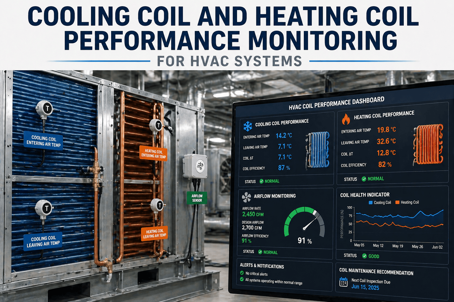
Measure and record entering air temperature (EAT) and leaving air temperature (LAT) across the coil under representative load conditions — log delta-T and compare to commissioned baseline. A narrowing delta-T indicates coil fouling, low refrigerant, or reduced airflow before any discharge temperature alarm triggers
Record: EAT/LAT reading with date and load conditions · Role: HVAC technician
For chilled water coils: measure and record entering water temperature (EWT) and leaving water temperature (LWT) — a narrowing water-side delta-T of 10% or more below baseline indicates coil fouling, flow restriction, or a failing control valve requiring investigation
Record: EWT/LWT reading with flow rate · Role: HVAC technician
Check and record airside static pressure drop across the coil face using a manometer — compare to commissioned pressure drop. A rise of 15% or more above baseline indicates fin blockage from particulates, lint, or biological growth before visible fouling is apparent on the face
Record: Pressure drop reading in Pa or in. w.g. with date · Role: HVAC technician
B. Quarterly — Physical Inspection
Access coil physically and inspect fin surface with flashlight — look for dust matting on face fins, biological growth (grey-green or black discolouration), bent or flattened fins reducing face area, and frost patterns indicating uneven refrigerant distribution in DX coils
Record: Inspection with condition description and photo evidence · Role: HVAC technician
Inspect condensate drain pan and drain line — confirm drain pan has no standing water, no biological growth (biofilm or algae), drain outlet is unobstructed, and drain slope is adequate. A blocked drain pan is the origin of the biological coil fouling cycle and a Legionella risk point
Record: Drain pan inspection with growth findings · Role: HVAC technician
For chilled water coils: inspect pipe connections, valves, and coil headers for scale, corrosion, or signs of leakage — confirm isolation valve function and that modulating control valve is operating through full stroke per BMS command
Record: Water-side inspection findings · Role: HVAC / pipework technician
C. Semi-Annual — Cleaning and Coil Treatment
Clean cooling coil using alkaline non-acid coil cleaner applied to fins — allow dwell time per product datasheet, rinse with low-pressure water directed opposite to normal airflow direction. Never use acid cleaners on aluminium fins; check fin material before selecting cleaning chemistry
Record: Cleaning work order with chemistry used and pre/post pressure drop reading · Role: HVAC contractor
Following cooling coil cleaning, disinfect drain pan and drain line with biocide — install drain pan treatment tablets rated for 90-day inhibition if biological fouling was found. Confirm drain flow rate with a simple pour test before closing access panel
Record: Biocide product name, concentration, and date applied · Role: HVAC contractor
Record post-cleaning delta-T and airside pressure drop — compare to commissioned baseline and to pre-cleaning readings. Cleaning that restores pressure drop to within 10% of baseline confirms coil is performing at design capacity; persistent elevation indicates deeper fouling or fin damage requiring deeper cleaning or replacement assessment
Record: Pre and post pressure drop values confirming cleaning effectiveness · Role: HVAC technician
Zone 02 — Heating Coils
Heating Coil Inspection — Hot Water & Steam Coils
Heating coils fail by a different mechanism than cooling coils. Corrosion from steam condensate, scale from untreated hot water circuits, and freeze damage from improperly protected low-temperature preheat coils are the primary failure modes — not particulate fouling. A hot water heating coil with 3 mm of internal scale on the tube walls transfers heat at roughly 40–60% of its clean surface capacity. Water treatment monitoring and annual tube-side inspection prevent the scale buildup that causes entire AHU heating sections to appear failed when the coil is simply blocked.
A. Monthly — Water-Side Performance Monitoring
Measure hot water supply and return temperatures across the coil — a reducing water-side delta-T (HWS–HWR) below 20–30% of design value indicates scale buildup inside tubes, low flow rate, or a short-circuiting bypass. Compare to the previous three months to identify trend, not just single reading deviation
Record: HWS and HWR temperature reading with ambient condition note · Role: HVAC technician
For steam coils: verify steam trap operation using an IR thermometer — a cold trap indicates blockage (no condensate removal, flooding the coil); a hot trap with flash steam visible downstream indicates a failed-open trap that is wasting steam and energy. Log steam trap condition for each unit
Record: Steam trap condition per trap with IR reading · Role: Pipework technician
B. Quarterly — Physical Inspection
Inspect heating coil fin surface for corrosion streaks (reddish-brown indicating steel tube corrosion), physical fin damage from cleaning or maintenance access, or evidence of freeze damage (expanded tubes, split headers) in low-temperature preheat coil applications
Record: Visual inspection with photo evidence of any corrosion found · Role: HVAC technician
Check low-temperature cutout setpoints for preheat coils — confirm mixed air temperature sensor is calibrated and the low-limit control shuts off outdoor air dampers before coil inlet temperature drops below 2°C (36°F). Freeze damage to heating coils is the highest-cost single maintenance event in cold-climate AHU systems
Record: Low-limit setpoint verification and sensor calibration check · Role: Controls technician
C. Annual — Tube-Side Inspection and Water Treatment
Test heating hot water circuit chemistry — pH target 8.0–9.5, inhibitor concentration at manufacturer specified range, conductivity within acceptable band. Out-of-specification water chemistry is the primary cause of internal tube scaling that cannot be detected by external inspection
Record: Water test results with comparison to specification · Role: Water treatment contractor
Flush heating coil headers and drain plugs to check for sediment accumulation — black or brown sediment in the flush indicates corrosion byproducts in the system requiring water treatment review and possibly magnetic filtration installation
Record: Flush sample description with photo if sediment found · Role: HVAC contractor
Oxmaint schedules delta-T trending checks and physical inspections per coil asset, trends performance against commissioned baseline, and auto-generates cleaning work orders when pressure drop or delta-T crosses the performance threshold you define.
Zone 03 — Condenser Coils
Condenser Coil Inspection — Air-Cooled Outdoor Units
Condenser coils operate outdoors in the highest-fouling environment in the HVAC system: airborne cottonwood seed, pollen, grass clippings, insect debris, and dust all accumulate on the fin surface between cleanings. Unlike evaporator coil fouling, condenser coil fouling is visible and rapid — a rooftop condenser in a cottonwood season can show a fully blocked face within two to four weeks. The consequence is elevated head pressure, increased compressor discharge temperature, and efficiency losses that compound across the cooling season.
A. Monthly — Outdoor Unit Inspection
Visually inspect condenser coil face for fin blockage — particularly during cottonwood/pollen season. If more than 20% of the visible face area is obstructed with debris, clean immediately rather than waiting for quarterly schedule. Blocked condenser coils raise head pressure faster than any other single factor
Record: Visual inspection with estimated obstruction percentage · Role: Building operator or HVAC technician
Check clearance around outdoor condenser units — confirm minimum 18-inch clearance on all sides, no vegetation growth, no debris accumulation under the unit, and no new shading structures installed above. Recirculation of hot discharge air reduces condenser efficiency by 5–15% and cannot be corrected by cleaning
Record: Clearance check with note of any new obstructions · Role: Building operator
B. Quarterly — Cleaning and Pressure Logging
Clean condenser coil fins with low-pressure water (max 100 PSI, 60° spray angle) directed from inside out — never high-pressure wash condensers, which permanently bends aluminium fins and reduces effective face area. For severely fouled coils use dedicated condenser coil cleaner foaming spray before rinsing
Record: Cleaning work order with pressure used and chemistry if applicable · Role: HVAC contractor
Record high-side refrigerant pressure under comparable ambient temperature conditions before and after cleaning — a head pressure drop of 20–50 PSI after condenser cleaning confirms the cleaning was necessary and effective. Log ambient temperature alongside head pressure reading for valid comparison
Record: Head pressure reading with ambient dry-bulb temperature · Role: Refrigeration technician
Inspect condenser fan motors for axle wobble, unusual noise, and blade damage — check motor amperage against nameplate. Condenser fan blade damage causes vibration that accelerates motor bearing wear and produces uneven airflow across the coil face, creating hot zones that elevate head pressure locally
Record: Motor amp reading and blade condition · Role: HVAC technician
Zone 04 — Performance Analytics
Coil Performance KPIs and the Analytics That Catch Fouling Before Capacity Loss
The seven KPIs below are the coil performance signals that separate facilities with documented performance trends from those discovering coil problems through tenant complaints and compressor failures. None of them require additional hardware if the HVAC system has BAS-connected temperature sensors and a CMMS that records readings with a timestamp per asset. Oxmaint's Preventive Maintenance platform captures all seven automatically from BAS data feeds or manual technician entry and trends them against each coil's commissioned baseline.
| Performance KPI |
What It Measures |
Trigger Threshold |
Corrective Action |
| Air-side delta-T (EAT – LAT) |
Cooling or heating capacity delivered per cfm |
>15% below commissioned baseline |
Inspect for fouling, low refrigerant, low flow |
| Water-side delta-T (EWT – LWT) |
Waterside heat transfer rate per GPM |
>10% below commissioned baseline |
Inspect for scale, control valve fault, flow imbalance |
| Airside pressure drop across coil |
Fin blockage and airflow restriction |
>15% above commissioned Pa drop |
Schedule coil cleaning, check filter loading |
| Compressor head pressure vs ambient |
Condenser coil fouling / recirculation |
Head pressure >15 PSI above expected at given ambient |
Clean condenser coil; check clearances |
| Drain pan water accumulation |
Drain line blockage and biological growth risk |
Standing water present after any 30-min dry period |
Clear drain, treat with biocide, check slope |
| Discharge air temperature at setpoint compliance |
Coil capacity to meet setpoint under load |
Discharge air consistently 1–2°C above setpoint |
Investigate coil fouling or refrigerant undercharge |
| Compressor amp draw trend |
Efficiency loss from fouled condenser or evaporator |
Amperage trending up >10% vs same season prior year |
Full coil inspection cycle; refrigerant check |
Expert Review
Why Coil Fouling Is an Analytics Problem, Not Just a Cleaning Problem
"The facility management teams that call me after a compressor failure because of 'a coil that nobody knew was blocked' all have the same pattern in their maintenance records: visual inspections on paper checklists marked 'clean' or 'okay', with no temperature readings, no pressure drop measurements, and no trend over time. You cannot detect mid-depth fin fouling by looking at the face of a coil. You detect it by watching the pressure drop across that coil rise 15% over three months while the face looks clean. You detect a blocked chilled water coil by noticing the water-side delta-T is 2.1°C when it commissioned at 3.8°C and understanding what that means. Coil condition monitoring is measurement work, not inspection work. The CMMS that captures those measurements and trends them per asset is the difference between catching fouling at the cleaning stage and catching it at the compressor replacement stage."
Dr. Maria Santos, PE, LEED AP BD+C
Licensed Mechanical Engineer · LEED Accredited Professional · 24 years HVAC systems commissioning and fault detection · Specialist in coil performance degradation diagnostics for commercial and healthcare facilities
FAQs
Frequently Asked Questions
How often should HVAC cooling and heating coils be cleaned?
Cooling coils in commercial buildings should be cleaned
semi-annually minimum, with quarterly inspection including delta-T and pressure drop measurements. Condenser coils require quarterly cleaning, and monthly visual checks during high-pollen or debris seasons. Heating coils require annual tube-side flushing and water chemistry testing.
Book a demo to see Oxmaint's coil PM schedule template.
What does a narrowing delta-T across a chilled water coil indicate?
A narrowing delta-T (entering water temperature minus leaving water temperature falling below commissioned design) indicates reduced heat transfer across the coil. The three most common causes are internal tube scaling from untreated water chemistry, reduced water flow rate from a faulty control valve or pump degradation, and airside fouling reducing the temperature driving force between air and water. Any single measurement below 10% of commissioned baseline triggers a full inspection cycle.
Can coil fouling cause a compressor to fail?
Yes, directly. Condenser coil fouling raises head pressure, which increases compressor discharge temperature and operating current. Sustained high-discharge-temperature operation degrades compressor oil, wears valve reeds, and ultimately causes motor winding failure. Evaporator coil fouling reduces suction pressure, causing the compressor to operate with elevated compression ratio — the same mechanical stress from the low-side. 25% efficiency loss from condenser fouling is documented before the system trips on a high-pressure cutout.
How does Oxmaint help track coil performance trends over time?
Each coil is registered as an individual asset with its commissioned baseline values — design delta-T, design pressure drop, design head pressure at rated ambient. Every technician entry or BAS data feed updates the performance trend for that asset. When delta-T narrows 10% or pressure drop rises 15%,
Oxmaint auto-generates a coil inspection work order before the performance loss triggers a capacity complaint or equipment failure.
Start a free trial to set up your first coil performance baseline.
Catch Coil Fouling at the Cleaning Stage, Not the Compressor Replacement Stage
Oxmaint's Preventive Maintenance platform schedules coil inspections on the right cadence, trends delta-T and pressure drop against each coil's commissioned baseline, and generates cleaning work orders automatically when performance drops below threshold — turning coil monitoring from a reactive scramble into a documented, continuous process.