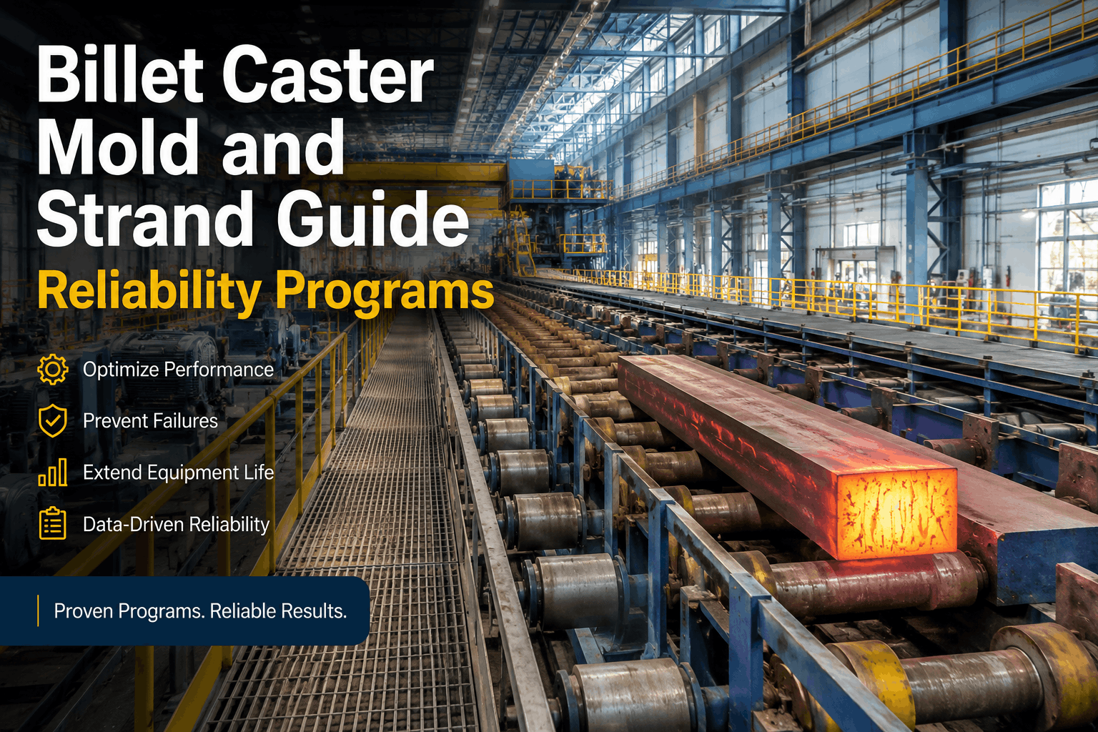
A continuous caster breakout — where the solidified shell fails and 1,520°C molten steel breaches onto the strand surface or secondary cooling zones — is one of the most catastrophic events in steel production. When liquid steel at 1,520°C flows over the copper mold and into the spray zones, it creates immediate safety hazard within 30 metres, stops the entire caster for 2–4 hours, damages equipment valued at millions, and produces scrap steel worth $50,000–$200,000 per breakout incident. Daily mold and strand guide inspection — verifying copper wear, oscillation stability, segment roll alignment, and spray nozzle condition — is the only defense that prevents breakouts before they happen. This checklist gives your caster operators a mobile-first framework for mold thermocouple trending, copper plate condition assessment, and spray nozzle coverage verification, integrated with OxMaint's CMMS breakout prevention system, converting tactile operator observations into predictive maintenance that eliminates 60–70% of unplanned breakouts before they occur.
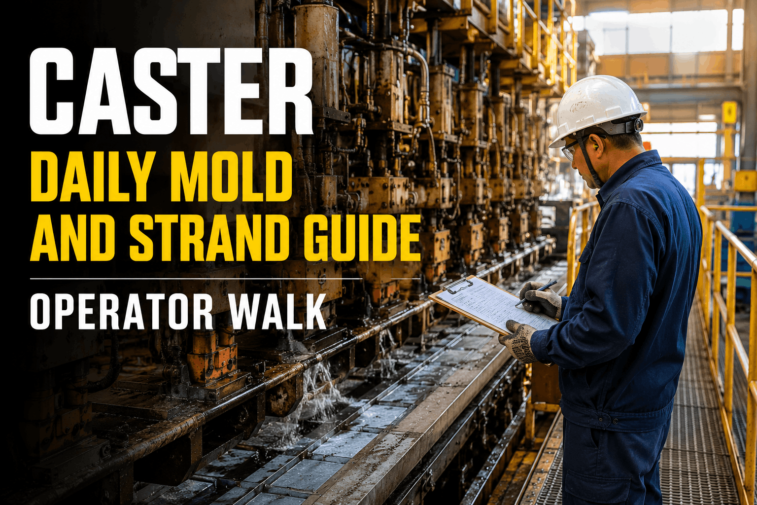
Continuous Caster Daily Mold and Strand Guide Operator Walk
Copper mold wear assessment, oscillation frequency verification, mold powder consumption tracking, segment roll alignment checks, and spray nozzle coverage mapping — structured for casters running 200–400 casts per week where every cast is a $15,000–$50,000 production event and one unplanned breakout erases the profit from 50+ casts.
Breakout Prevention Is Non-Negotiable
A caster breakout occurs when the solidifying shell fails — releasing molten steel at 1,520°C onto the casting deck. Detection window from shell failure to catastrophic breakout: 0.5–2 seconds. Only early detection of sticker-type breakouts via mold thermocouple pattern recognition provides warning time for strand stop. Daily mold inspection detects conditions 4–8 hours before stickers develop.
Mold Copper Plate Wear and Condition
The mold copper plates are where strand shell formation begins — a water-cooled copper interface that directly contacts molten steel at 1,520°C and withdraws heat at rates exceeding 100 MW. Copper wear from friction with the solidifying shell, thermal cycling, and slag chemistry attack reduces campaign life by hundreds of heats if undetected. Campaign extension requires daily wear rate tracking and predictive plate replacement planning.
Copper Wear Rate
Track per-cast wear; replace at campaign wear limit
Mold Level Control
Maintain ±2 mm of target; oscillation <5 mm
Heat Extraction
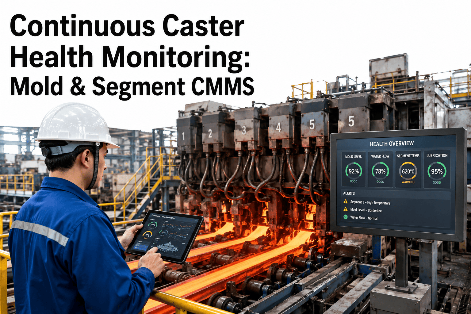
Monitor thermocouple patterns for sticker early warning
Oscillation System and Mold Motion
Mold oscillation — reciprocating the copper mold 60–400 cycles per minute — creates a lubricating film between the mold and solidifying shell that prevents breakouts. Oscillation amplitude and frequency drift create friction imbalance — generating oscillation marks on the strand surface and increasing sticker breakout risk. Daily oscillation verification catches system degradation before friction builds.
Strand Guide Segment Rolls and Alignment
Strand guides maintain the strand geometry as it travels through secondary cooling zones — preventing surface defects and internal stress. Segment roll wear, misalignment, or bearing degradation creates lateral strand forces that damage surface quality and, in extreme cases, can cause strand breakout. Daily alignment checks prevent guide-induced breakouts and surface defects.
Mold and Strand Guide Daily KPI Matrix
| Inspection Element | Measurement | Target / Limit | Frequency |
|---|---|---|---|
| Mold Copper Plate Wear | Visual + dimensional gauge | <1 mm/500 heats | Shift / Weekly |
| Mold Cooling Water Flow | Flowmeter at inlet | 150–250 GPM ±10% | Per Cast |
| Mold Level Sensor Accuracy | Sensor vs manual gauge | Within ±2 mm | Per Cast |
| Oscillation Frequency Accuracy | OsciChecker laser tool | ±2% of setpoint | Shift Start |
| Oscillation Stroke Amplitude | Laser displacement sensor | Within ±0.2 mm target | Shift Start |
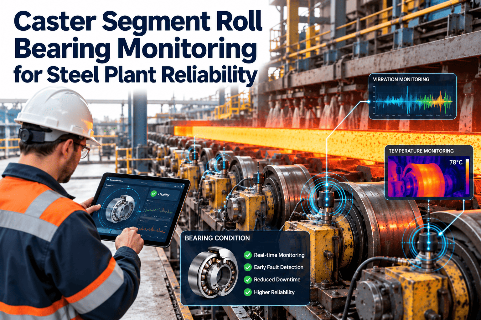
| Strand Guide Roll Bearing Vibration | Accelerometer trending | <Alert threshold | Weekly |
| Strand Guide Lateral Alignment | OPAL laser alignment | Within ±5 mm centerline | Shift Start |
Secondary Cooling Spray Nozzle Coverage
Secondary cooling zones apply water spray to the strand surface as it solidifies — controlling cooling rate, preventing surface cracks, and managing internal stress. Blocked spray nozzles, uneven spray pattern, or nozzle valve failure creates dry zones on the strand surface that develop thin-shell breakout risk. Daily spray coverage verification prevents cooling-related breakouts.
"Before OxMaint, we caught breakouts after they happened — dealing with the disaster instead of preventing it. Now our caster operators log mold copper wear and thermocouple patterns every heat. Last month we detected a sticker precursor 6 hours before the AI algorithm would have flagged it — caught visible copper deformation that was causing friction buildup. We stopped the heat, re-optimized mold powder, and avoided a $150K breakout scrap loss. Daily mold inspection converted operators from reactive firefighters to predictive maintenance resources."
Frequently Asked Questions
What is the difference between a sticker-type breakout and a surface-level breakout, and why does early warning matter?
Sticker breakout occurs when the solidified shell sticks to the mold copper due to friction buildup — detected 2–8 seconds before shell failure via mold thermocouple pattern analysis. Surface breakout has <0.5 second warning — virtually no time to react. Early sticker detection enables strand stop before catastrophic failure.
How does mold taper wear increase sticker breakout risk, and what's the replacement criteria?
Mold taper allows shell to separate from copper as strand descends. Worn taper creates uneven separation — increasing friction in some zones and reducing film strength in others. Replacement at <0.5 mm taper deviation prevents friction-induced stickers and extends copper campaign life.
What does oscillation mark depth >0.3 mm on the cast product indicate about mold condition?
Oscillation marks >0.3 mm deep signal friction imbalance or amplitude drift — creating surface defects and reducing steel grade. Indicates mold oscillation system needs frequency/stroke verification and possible servo valve or spring replacement before continued casting.
How often should copper mold plates be replaced, and what's the typical campaign life?
Campaign life depends on steel grade and casting speed: premium grades 300–600 heats; commodity grades 800–1,200 heats. Replacement triggered when copper wear approaches wear limit (~1 mm per 500 heats) or taper deviation exceeds ±0.5 mm — whichever comes first.
What's the consequence of mold level oscillating ±5 mm around setpoint instead of ±2 mm?
Mold level oscillation >±5 mm indicates SEN blockage or ladle flow instability — causing uneven mold powder distribution and variable heat extraction. This creates sticker initiation zones and thin-shell defects, increasing breakout probability by 4–6x.
Why is strand guide alignment checked with laser tools rather than manual measurement methods?
OPAL laser alignment provides ±1 mm accuracy vs ±5 mm for manual methods — necessary precision to detect the 5 mm misalignment threshold that creates lateral strand forces and surface damage. Manual methods miss early-stage misalignment until damage becomes visible in the product.
What is the cost impact of a single caster breakout incident, and how many breakouts per month is typical without predictive maintenance?
Single breakout: $50K–$200K in scrap steel, $50K–$100K in equipment repair, 2–4 hours lost production = $300K–$400K total impact. Plants without structured mold inspection average 2–4 breakouts per month. Daily inspection typically reduces this to <1 breakout per month.
How does OxMaint's breakout prediction algorithm work, and what's the required warning time for strand stop to prevent disaster?
Algorithm analyzes 100–300+ mold thermocouples per second — detecting characteristic temperature signatures 2–8 seconds before shell failure. Strand stop (emergency power cutoff to caster motors) requires <0.5 second response time. Eight-second warning provides 16x the reaction time needed.
Every Mold Inspected. Every Thermocouple Trending. Every Breakout Prevented.
OxMaint's daily caster inspection app captures mold copper wear, oscillation performance, strand guide alignment, and spray nozzle coverage with mobile timestamped sign-off — converting operator observations into breakout prevention intelligence that eliminates 60–70% of unplanned breakouts and extends mold campaigns by 200+ heats per season.