The Electric Arc Furnace (EAF) is where modern steel is born — three graphite electrodes carrying 50,000–80,000 amps melting scrap into liquid steel within 40–65 minutes per heat. But that arc operates at 3,000°C at the electrode tip, creating extreme thermal stress on water-cooled sidewall panels, refractory-lined hearth, and cooling systems where a single failure — a leak in electrode arm cooling, a panel breach, or a refractory hotspot going undetected — turns a profitable furnace into a shutdown liability. An EAF that melts for 20 years generates $400–800M in cumulative revenue; one unplanned reline at $2–4M and 7–14 days downtime erases months of profit. Daily pre-heat inspections that capture electrode alignment, water-cooled panel temperature trending, transformer tap position, and scrap charging condition — recorded in OxMaint's mobile-first CMMS — are the only defense between consistent profitable production and the unplanned shutdown that costs more than the entire year's maintenance budget.
EAF Daily Pre-Heat Operator Round Checklist
Electrode position verification, water-cooled panel leak detection, transformer tap trending, scrap charging preparation, and emergency cooling system checks — structured for melting shops where every heat delivers $15,000–$30,000 in revenue and missing one day of production costs $300,000–$500,000.
A cooling water leak into an EAF containing molten steel creates a steam explosion with catastrophic consequence. Daily pre-heat cooling system checks are not optional — they are safety-critical requirements where missing one inspection can cost lives.
Electrode Position and Column Integrity
Three graphite electrode columns are the furnace's only path for electrical energy — positioned to melt scrap pile while maintaining stable arc without touching the refractory sidewalls. Electrode misalignment of >20 mm, column joint deterioration, or stub nipple wear cascades into mid-heat electrode breakage that stops production for 2–4 hours and can damage the refractory roof from arc instability.
Electrode Position Check
Verify tip alignment within ±10 mm of baseline during roof swing
Joint Integrity
Check nipple connections for cracks or separation before melt
Consumption Trending
Track electrode length loss per heat; flag abnormal rates
Water-Cooled Panel System
Water-cooled sidewall panels handle 80% of the furnace's thermal load — protecting the furnace shell from the 3,000°C arc zone. Panel leaks, restricted cooling flow, or burst hoses during a heat create steam explosions and catastrophic furnace damage. Daily cooling system verification is the highest-consequence safety check on the EAF floor.
Emergency Cooling System Response Protocol
If cooling water flow drops >20% from baseline during melt operation: (1) Immediately reduce furnace power to 50%; (2) Page emergency maintenance; (3) Prepare for furnace power-down if flow not restored within 30 seconds; (4) NO continued operation without full cooling flow — steam explosion risk is unacceptable.
Transformer and Electrical Power Delivery
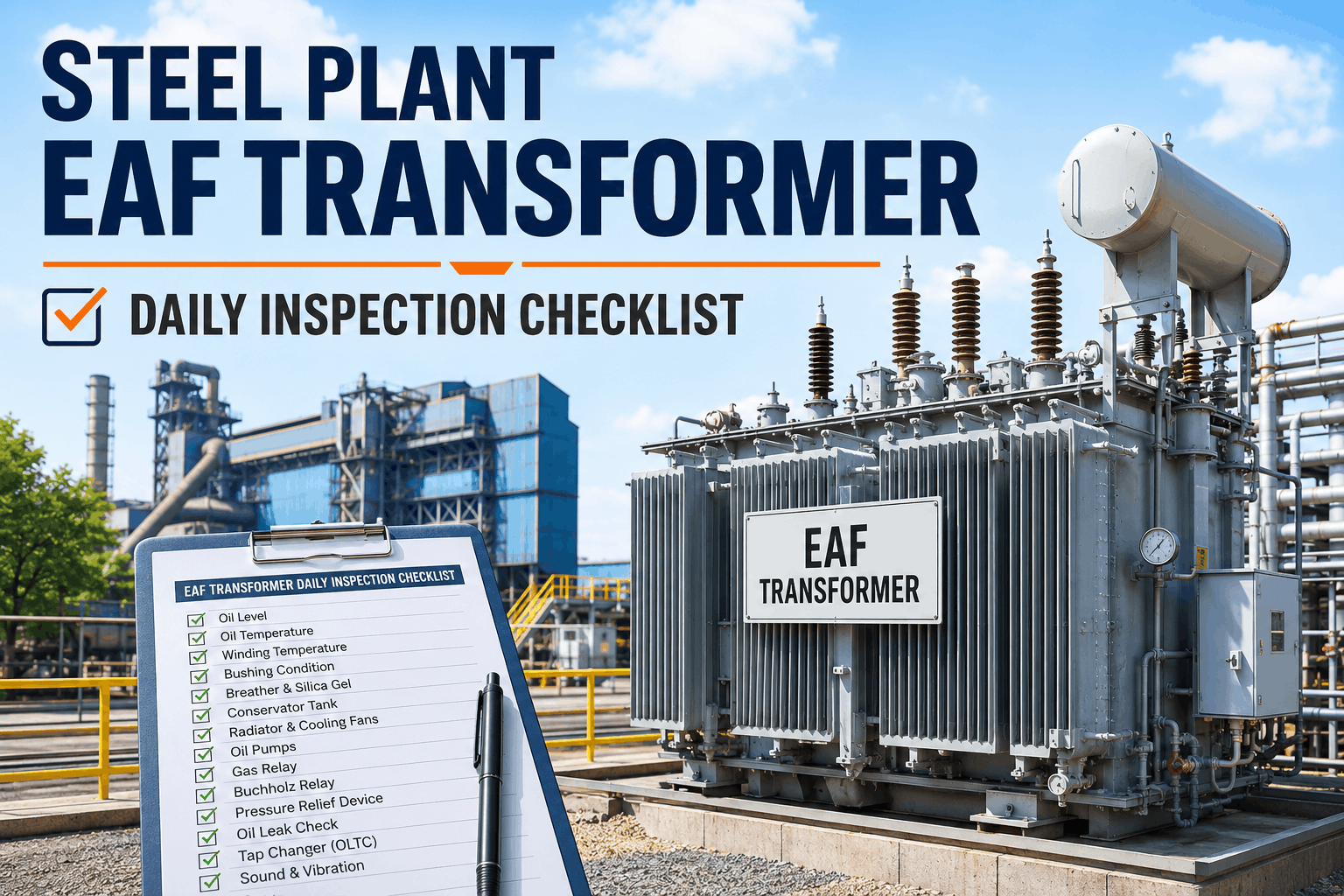
The EAF transformer steps down grid voltage (33–138 kV) to 500–1,000V secondary — delivering 50,000–80,000 amps into the furnace. Transformer tap position controls secondary voltage; loose electrical connections generate heat and resistance rise; power factor correction capacitor degradation reduces apparent power — all cascading into reduced melting efficiency and extended tap-to-tap times that cost production.
Scrap Charging Preparation and Burden Assessment
Scrap mix quality, density, and contamination directly impact melting efficiency — low-density scrap takes longer to melt and extends tap-to-tap time; contaminated scrap (copper, tin, stainless) creates bath chemistry problems requiring ladle refining and lost production time. Pre-charge scrap assessment identifies quality issues before they compound into furnace delays.
EAF Pre-Heat Daily Checklist Summary
| Inspection Element | Check Method | Target / Limit | Frequency |
|---|---|---|---|
| Electrode Position Alignment | Measurement from reference points | Within ±10 mm baseline | Roof Swing |
| Cooling Water Supply Pressure | Gauge at pump discharge | 2–3 bar ± 0.2 bar | Before Charge |
| Panel Exit Water Temperature | Non-contact thermometer | ≤45°C above inlet | Before Charge |
| Electrode Consumption Rate | Length loss per heat measured | <3.5 kg/tonne | Per Heat |
| Transformer Tap Position | DCS tap indicator verified | No deviation from baseline | Before Charge |
| Power Factor Ratio | kVA vs kW trending | ≥0.95 power factor | Per Heat |
Furnace Shell and Refractory Condition Assessment
The furnace shell and refractory form the structural containment vessel for the 3,000°C arc zone. Shell temperatures >120°C in specific zones indicate refractory thinning in that area — requiring accelerated wear tracking and planned lining repair scheduling before structural failure risk develops and forces emergency furnace shutdown.
"Before going digital with OxMaint, we discovered cooling panel leaks after they'd already been running hot for 30+ minutes — risking steam explosion. Now our operators check cooling system flow and temperature before every charge. Last month we caught a flex hose starting to weep during pre-heat inspection, replaced it during roof swing, and prevented a catastrophic failure. That one early detection paid for the entire year of OxMaint. It's not just efficiency — it's safety."
Frequently Asked Questions
Why is water-cooled panel cooling verification done BEFORE scrap charging rather than during operation?
A cooling leak discovered during a 3,000°C melt creates a steam explosion with catastrophic consequence. Pre-charge verification confirms cooling system is healthy and safe before risk exposure begins. There is no acceptable level of deferred cooling system repairs.
What electrode consumption rate is acceptable for typical scrap-based EAF operations?
Acceptable consumption is 2.0–3.2 kg/tonne depending on scrap type and melt rate. Rates >3.5 kg/tonne signal mid-heat electrode breakage risk, accelerated joint wear, or misalignment problems requiring investigation and corrective action.
How does electrode regulation response time affect melting efficiency and electrode safety?
Regulation system maintains electrode depth within ±5 mm of setpoint — fast response prevents electrode-to-wall contact that damages refractory and slows heat transfer. Regulation lag >3 seconds indicates servo valve wear requiring immediate maintenance before electrode breakage develops.
What does abnormally low EAF power factor (below 0.90) indicate, and what's the production impact?
Low power factor indicates reactive power loss from degraded power factor correction capacitors — increasing electrical losses and extending tap-to-tap time by 3–5 minutes per heat. Over 20+ heats/day, this adds 1+ hour of lost production daily. Capacitor bank maintenance is priority maintenance action.
How should operators respond if they detect loose flex hoses during roof swing inspection?
Any flex hose showing bulging, corrosion, or moisture is marked for replacement. Zero tolerance for deferred hose repairs — hose replacement is completed during the roof swing maintenance window before next scrap charging. Running a heat with marginal hose is unacceptable safety and production risk.
What is the significance of electrode joint nipple deterioration, and when should joints be replaced?
Nipple joints connect consumable graphite to metal stub — joint cracking indicates thermal fatigue and joint separation risk. Failure mid-heat requires 2–4 hour rod change shutdown. Joint replacement is performed at first sign of cracking — before failure disrupts production.
How does OxMaint's EAF checklist link pre-heat observations to production scheduling and scrap procurement?
OxMaint captures scrap source, density, composition flags, and metal content in each heat record — linked to final steel analysis and quality data. Over time, this creates feedback loop showing which scrap suppliers deliver consistent composition, density, and melting efficiency — optimizing both procurement and melting performance.
What is the minimum action required if shell temperature survey shows a 25°C hotspot in the sidewall zone?
A +25°C hotspot indicates refractory thickness has fallen below acceptable levels. Immediate action: schedule ultrasonic thickness measurement at hotspot; reduce furnace power if hotspot persists >2 shifts; order accelerated lining repair or full reline depending on thickness findings; suspend normal operations if thickness below minimum.
Every Electrode Aligned. Every Cooling Flow Verified. Every Refractory Trending Visible.
OxMaint's daily EAF pre-heat checklist captures electrode position, water-cooled panel temperatures, transformer tap trending, and refractory hotspot detection with mobile timestamped sign-off — converting operator observations into predictive maintenance that prevents electrode breakages, cooling failures, and the unplanned 7–14 day relines that cost $2–4M per incident.