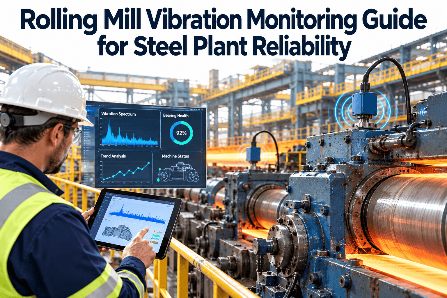
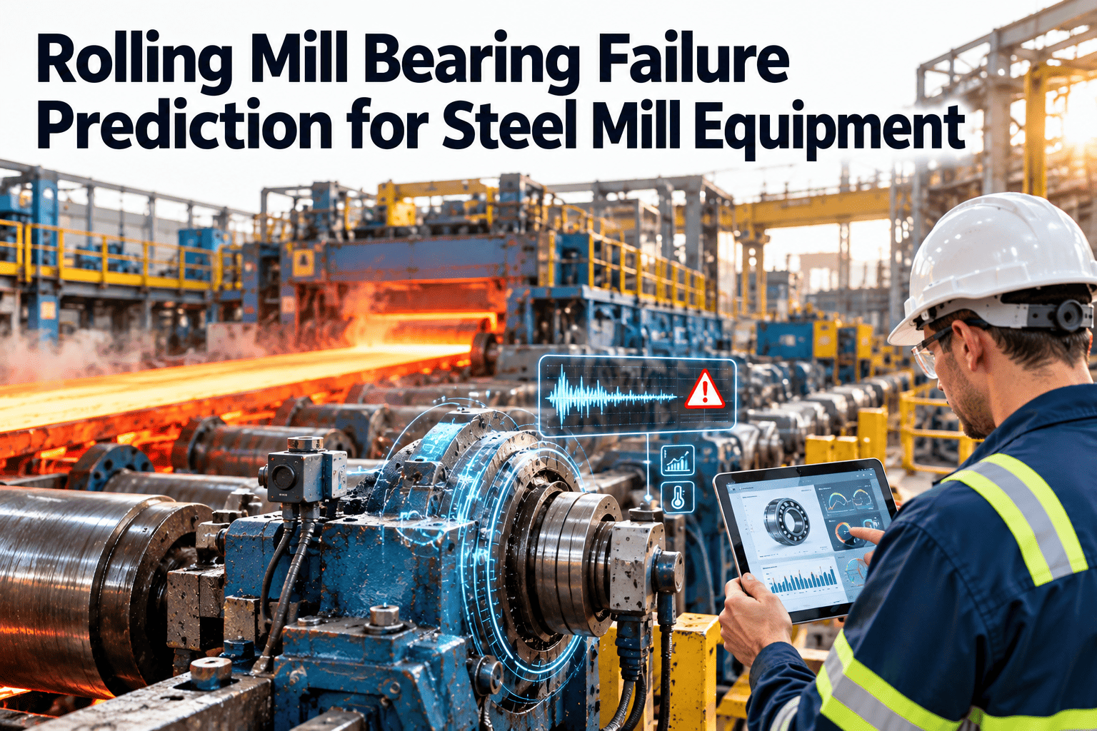
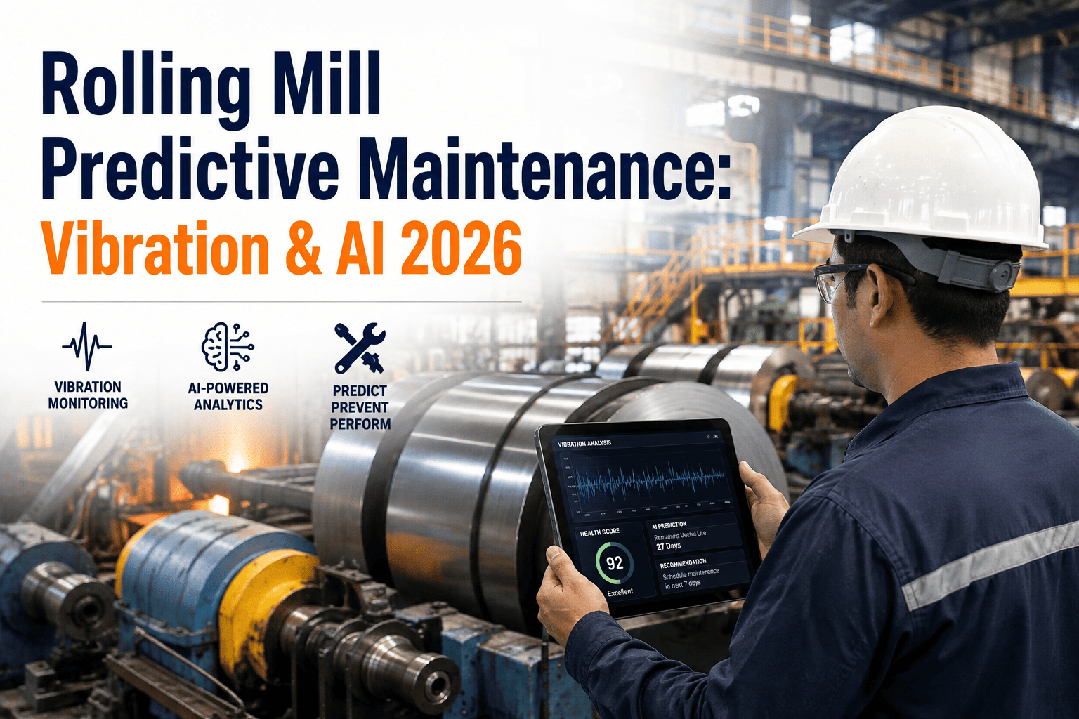
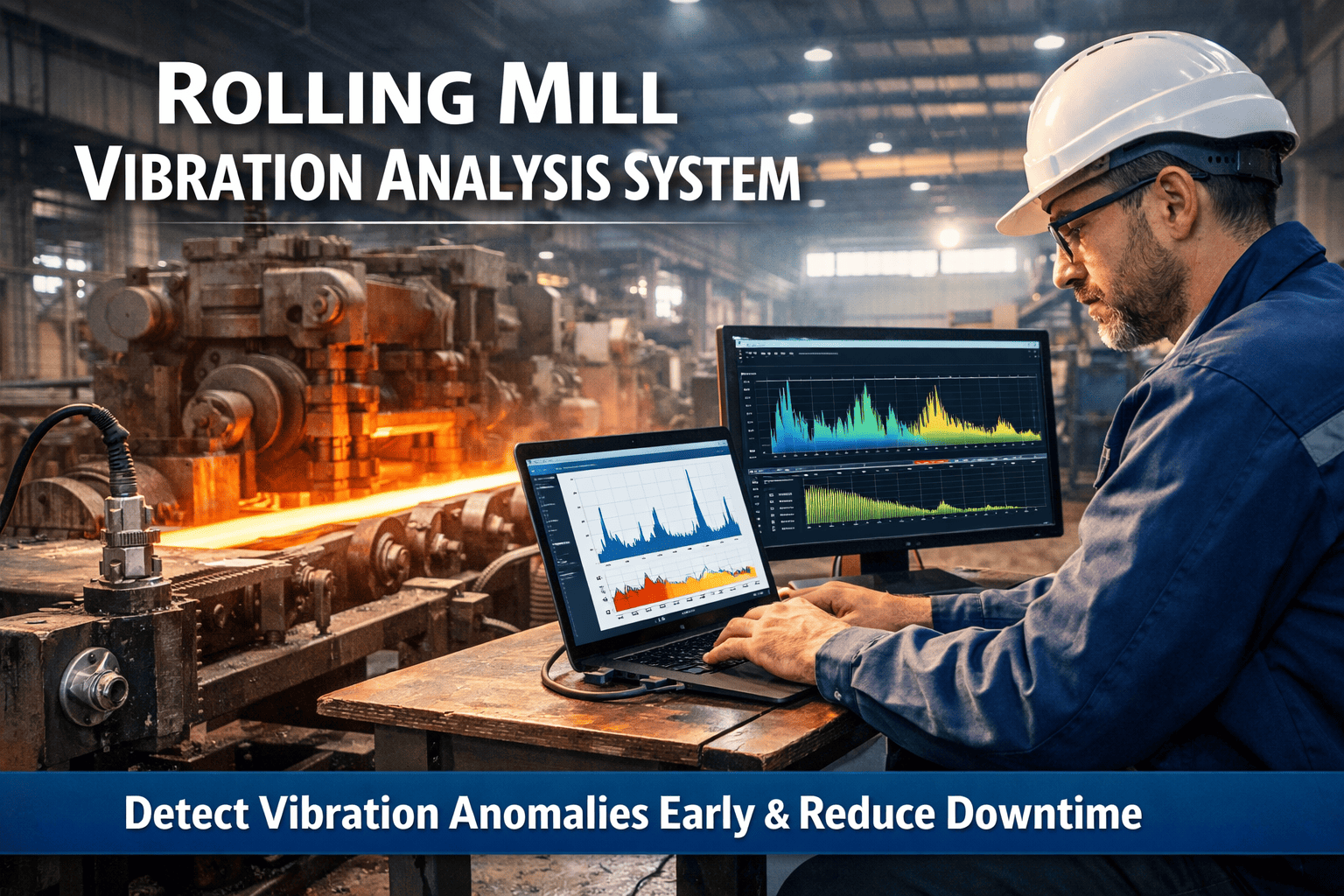
A rolling mill bearing that reaches Stage 4 failure — visible spalling, broadband noise floor rising, housing running hot — has been broadcasting its condition for weeks. The BPFO harmonic series was present in the frequency spectrum for four to eight weeks before the bearing noise became audible. The temperature rose above baseline by 12°C three days before the shaft seized. None of those signals generated a work order because no one was trending them. The bearing failed on a Saturday afternoon during a hot strip campaign. The pass schedule was aborted, the roll had to be emergency-changed, and the stand was offline for six hours. Start trending your mill bearing vibration in Oxmaint free — every bearing has a failure signature. The question is whether your system is reading it.
Rolling Mill Bearing Maintenance: Vibration Monitoring and Predictive Failure Detection
BPFO and BPFI defect frequency detection · bearing damage stage progression · chock and backup roll bearing monitoring · CMMS-automated work orders from sensor thresholds
Act at Stage 1–2. Stage 3 requires urgent scheduling. Stage 4 means emergency replacement.
The Four Stages of Rolling Mill Bearing Failure — and What to Do at Each One
Every rolling element bearing fails through the same four-stage progression. Understanding which stage your bearing is in determines the correct maintenance response — from planned replacement window in Months 1–3 at Stage 1, to emergency stand change within hours at Stage 4. The practical skill is learning to read which stage is indicated by the combination of vibration spectrum content, overall amplitude, temperature, and oil analysis.
Sub-surface Micro-cracking
Detection window: 1–3 monthsMicroscopic cracks forming below the race surface from rolling contact fatigue. No macroscopic damage yet. Overall vibration levels remain within normal range.
Ultrasonic or high-frequency envelope analysis above 250 kHz. Slight increase in mechanical noise floor at bearing defect frequency harmonics. Oil analysis may show sub-micron metallic particle increase.
Flag for close monitoring. Plan bearing replacement in next scheduled roll change. Increase sampling frequency to weekly. No emergency action required.
Early Pitting — Bearing Fault Frequencies Emerge
Detection window: 2–6 weeksSmall pits appearing on race surfaces. BPFO or BPFI components become visible in envelope analysis spectrum. Slight increase in high-frequency energy. Overall vibration levels may still be acceptable by absolute threshold.
BPFO peaks at calculated defect frequency with up to 3 harmonics. BPFI appearing with 1× RPM sidebands — characteristic of inner race damage entering the load zone cyclically. Defect amplitude below 0.1 in/s indicates months remaining.
Generate scheduled replacement work order. Target next roll change or planned stand outage. Increase monitoring to twice weekly. Sign up for Oxmaint to configure Stage 2 threshold alerts with automatic work order generation.
Established Defect — Harmonics and Sidebands Present
Detection window: Days to 2 weeksMultiple harmonics of BPFO or BPFI visible in standard FFT spectrum (8–10 harmonics). Sideband harmonics spaced at 1× RPM around BPFI harmonics confirm active inner race damage in the load zone. Defect audible with ultrasonic probe. Overall vibration rising noticeably above baseline.
Defect amplitude 0.1–0.3 in/s with extensive sidebands: 2–8 weeks remaining. At 0.3–0.5 in/s with broadband noise beginning to rise: days to two weeks. Temperature rising above baseline by 8–15°C. Oil analysis showing elevated iron and copper wear metals.
Escalate to priority work order. Replacement must happen at the next available stand outage — do not defer beyond the next maintenance window. Daily monitoring minimum. Alert engineer on shift by name. Book a demo to see escalation routing in Oxmaint.
Catastrophic — Immediate Failure Risk
Remaining window: HoursVisible spalling. Rolling elements partially following spall profile, generating vibration at bearing defect frequencies from mechanical deformation, not elastic wave propagation. High overall vibration, broadband noise floor rise, audible noise, housing running hot. Random high-frequency spikes indicate imminent catastrophic failure.
Overall vibration above 0.5 in/s with broadband noise. Bearing temperature more than 25°C above baseline. Multiple fault frequencies with extensive sidebands in standard spectrum. Stand may show vibration perceptible to touch. Speed-dependent noise changes confirm bearing origin.
Emergency stand change. Do not continue the pass schedule. The risk of chock bearing catastrophic failure during rolling includes roll damage, mill housing damage, and operator safety events. Cost of emergency change is orders of magnitude less than a locked bearing under rolling load.
Reading BPFO, BPFI, BSF, and FTF Signatures in Rolling Mill Bearing Spectra
Each bearing component produces a characteristic defect frequency when damaged. These frequencies are calculated from bearing geometry and shaft speed — they are not harmonics of running speed, which is why they stand out clearly in the FFT spectrum. Rolling mills run at known, relatively stable speeds during campaigns, which makes bearing defect frequency tracking straightforward: calculate the four defect frequencies for each bearing designation at the operating speed, load them into your monitoring system, and alert when amplitude at those frequencies rises above baseline by a defined threshold.
Connect your bearing sensors to automated work orders
Oxmaint loads your bearing defect frequencies from bearing designation, monitors amplitude at each frequency every measurement cycle, and generates a prioritised work order the moment a Stage 2 threshold is crossed — before the bearing reaches Stage 3.
Rolling Mill Bearing Types: Monitoring Priorities by Position
Rolling mills use different bearing types at different positions, each with distinct failure modes, monitoring access constraints, and criticality. Work roll chock bearings are replaced at every roll change — monitoring is still valuable for detecting abnormal degradation before the scheduled change. Backup roll chock bearings run for extended campaigns and represent the highest-cost bearing failure event in the mill. Pinch roll, entry/exit guide, and drive stand bearings require ongoing route-based monitoring.
| Bearing Position | Typical Type | Primary Failure Mode | Monitoring Method | Key Threshold | CMMS Action |
|---|---|---|---|---|---|
| Work roll — chock bearing | 4-row tapered roller (TDO/TQO) | BPFO outer race fatigue under concentrated radial load | Portable route every roll change + temperature | Any Stage 2 BPFO before scheduled change | Flag for change at next scheduled roll swap |
| Backup roll — chock bearing | 4-row cylindrical or tapered roller | BPFO / BPFI at high load — long campaign exposure | Online continuous + portable confirmation | Stage 2 = schedule. Stage 3 = urgent outage | Stage 3 escalation: priority work order, engineer alert |
| Pinch roll bearing | Spherical roller or cylindrical | Misalignment-induced BPFI, contamination from scale | Route-based portable — monthly minimum | 2× running frequency (misalignment) + BPFI | Alignment check before bearing replacement WO |
| Mill drive stand gearbox bearing | Cylindrical + thrust roller | BSF + gear mesh interaction — complex spectrum | Online with gear mesh frequency separation | Bearing amplitude rising independent of gear mesh | Bearing defect WO separate from gear inspection WO |
| Entry/exit guide roll bearing | Deep groove ball or needle roller | Contamination, inadequate lubrication, impact load | Route-based — weekly visual + monthly portable | Temperature above 15°C over ambient baseline | Temperature-triggered work order — lubrication check first |
| Coiler/tension reel bearing | Spherical roller or tapered roller | BPFO under mandrel expansion/collapse cycling | Online or route — condition-based interval | BPFO amplitude rising above baseline trend | Condition-triggered work order — schedule in coiler outage |
Swipe to view all columns on mobile
What to Monitor, What to Trend, and What Triggers a Work Order
| Parameter | Instrument | Stage 2 Alarm | Stage 3 Alarm | Emergency Trip | CMMS Trigger |
|---|---|---|---|---|---|
| Overall vibration velocity (radial) | Accelerometer — bearing housing | Rising trend >20% above baseline | 0.3 in/s with sidebands | >0.5 in/s broadband noise | Trending alert → scheduled WO |
| BPFO amplitude | Spectrum analyser — envelope analysis | BPFO peak 3 dB above noise floor | 3+ harmonics visible in standard FFT | 8+ harmonics with sidebands | 3+ harmonics → urgent WO generated |
| BPFI amplitude with 1× sidebands | Spectrum analyser — envelope analysis | BPFI peak with 1× RPM sideband emerging | Multiple BPFI harmonics + sideband family | Extensive sideband harmonics visible | Sideband family confirmed → urgent WO |
| Bearing housing temperature | RTD or contact thermometer | +8°C above established baseline | +15°C above baseline | +25°C above baseline or OEM absolute limit | +8°C rise rate trigger → check lube first |
| BSF + FTF amplitude | Spectrum analyser | BSF peak above noise floor | BSF with FTF sidebands visible | All four frequencies present simultaneously | FTF modulating BPFO → Stage 3 WO escalation |
| Oil analysis — wear metals | Laboratory — ICP spectrometry | Fe >50 ppm or Cu >20 ppm | Fe >100 ppm or rising two consecutive samples | Sudden particle count spike — immediate | Quarterly oil sample PM + threshold alert WO |
| Lubrication oil pressure and flow | Pressure transmitter + flow meter | Flow below 90% of baseline | Pressure below OEM minimum | Flow loss to any bearing | Any pressure loss → immediate work order |
Swipe to view all columns on mobile
How Oxmaint Vibration Analysis and Predictive AI Serve Mill Bearing Teams
Bearing Defect Frequency Tracking Per Asset
Load bearing designation, geometry, and operating speed into Oxmaint for each bearing asset — chock, backup roll, pinch roll, drive stand. The system calculates BPFO, BPFI, BSF, and FTF for that bearing at that speed. When sensor readings arrive, amplitude at each defect frequency is checked against both absolute thresholds and trending baselines. Stage 2 detection triggers a scheduled work order. Stage 3 triggers an escalated priority alert. Sign up free to configure defect frequency tracking for your mill bearing fleet.
Condition-Normalised Trending — Eliminating Amplitude False Alarms
Rolling mill bearing vibration amplitude changes with rolling load, strip thickness, speed, and temperature. A fixed amplitude threshold generates false alarms at high rolling loads and misses real degradation at low loads. Oxmaint normalises vibration readings against rolling schedule parameters — speed, rolling force, and strip gauge — to build a condition-specific baseline per bearing. A genuine Stage 2 BPFO amplitude increase registers as an anomaly regardless of the operating condition it occurred in. Book a demo to see condition-normalised trending.
Oil Analysis Integration and Wear Metal Trending
Quarterly bearing oil analysis results — Fe, Cu, Al, Cr particle counts; viscosity; acid number — are logged per bearing asset in Oxmaint against the rolling hours accumulated since the last sample. Rising Fe trend across two consecutive samples at the same bearing triggers a correlated alert alongside the vibration data, giving the diagnostics team both the frequency domain evidence and the metallurgical confirmation before they commit to an unscheduled stand change. Start free to configure oil analysis records linked to bearing assets.
Roll Change Work Package — Bearing Inspection Items Pre-loaded
When a roll change work order is generated, Oxmaint pre-loads the bearing inspection items for that stand automatically: chock bearing visual inspection, seat measurement, housing bore check, and lube passage verification. The technician completes the bearing inspection as part of the roll change — not as a separate activity that gets deferred. Bearing condition findings from every roll change build the individual bearing history used for predictive replacement decisions. Book a demo to see roll change work package configuration.
Bearing fault frequencies only appear clearly in Stage 4 in standard FFT spectra — but detectable signals in envelope analysis appear 6–8 weeks earlier. The difference between detecting at Stage 2 and Stage 4 is the difference between a planned bearing swap at the next roll change and an emergency stand change during a hot strip campaign. The maintenance cost difference is an order of magnitude. The scheduling difference is the difference between a planned hour and an unplanned day.
Frequently Asked Questions
How are BPFO and BPFI calculated for rolling mill chock bearings?
BPFO approximates to 0.4 × NB × RPM and BPFI to 0.6 × NB × RPM, where NB is the number of rolling elements. Precise values require the full bearing geometry including pitch diameter, roller diameter, and contact angle — available from the bearing manufacturer's datasheet. Most major bearing manufacturers (SKF, NSK, FAG/Schaeffler) provide free online calculators. For rolling mills where speed varies by pass, configure your monitoring system to recalculate defect frequencies at each measured RPM value rather than using a fixed speed. Load the bearing designation and operating speed range into Oxmaint — the system maintains the defect frequency library per bearing asset and recalculates as speed changes. Sign up free to configure bearing defect frequencies in your asset records.
How do you distinguish bearing defect frequency signals from gear mesh frequencies in a mill drive gearbox?
Gear mesh frequency is calculated as number of teeth × RPM and appears as a non-harmonic frequency in the spectrum alongside its sidebands. Bearing defect frequencies (BPFO, BPFI, BSF, FTF) are also non-harmonic. The distinction requires knowing the calculated value of each — load the gear tooth counts and bearing designations for the gearbox into Oxmaint so that every peak in the spectrum can be attributed to a known source. A rising amplitude at a calculated bearing defect frequency that is not accompanied by changes in the gear mesh family indicates a bearing issue independent of gearbox condition. A rising gear mesh amplitude with sideband growth indicates a gear condition issue. Both should generate separate work orders with separate diagnostic tracks. Book a demo to see gearbox frequency attribution in Oxmaint.
What is the right monitoring interval for work roll chock bearings given that they are changed every roll change?
The value of monitoring work roll chock bearings is not preventing an emergency bearing failure — it is detecting abnormal degradation that indicates the bearing is running in an adverse condition (misalignment, overload, lubrication failure, contaminated seat) that will repeat on the next set if not corrected. A bearing that shows Stage 3 BPFO after only 200 heats when the normal life is 800+ heats is telling you something about the chock condition, the roll neck condition, or the lubrication supply. Portable route-based measurement at every roll change takes approximately 3 minutes per chock. The data goes into the bearing's CMMS record alongside the roll change findings. Patterns of premature degradation in specific stand positions identify recurring mechanical issues. Start free to configure per-roll-change bearing inspection records.
When is a temperature rise from a bearing housing indicative of bearing damage versus lubrication issues?
Temperature rise alone cannot distinguish between bearing damage and lubrication deficiency. Both produce rising housing temperature. The diagnostic sequence is: (1) check lube system — pressure, flow, and supply temperature — before attributing temperature rise to bearing damage. If lube supply is normal and temperature is still rising, move to (2) vibration spectrum analysis for defect frequencies. A bearing with BPFO harmonics in Stage 2 alongside a temperature rise of +10°C is a confirmed bearing condition issue. A temperature rise with normal vibration spectrum and confirmed adequate lubrication supply could indicate bearing overload, incorrect bearing fit, or thermal path issues. Log all three data streams — temperature, vibration, and lube system parameters — in the same work order so the diagnostics team has the full picture. Oxmaint links all three to the bearing asset record for correlated analysis.
Connect Your Mill Bearing Sensors to Automated Predictive Work Orders
BPFO and BPFI defect frequency tracking, condition-normalised trending, oil analysis records, and roll change bearing inspection packages — all in Oxmaint, connected to your existing sensor infrastructure.