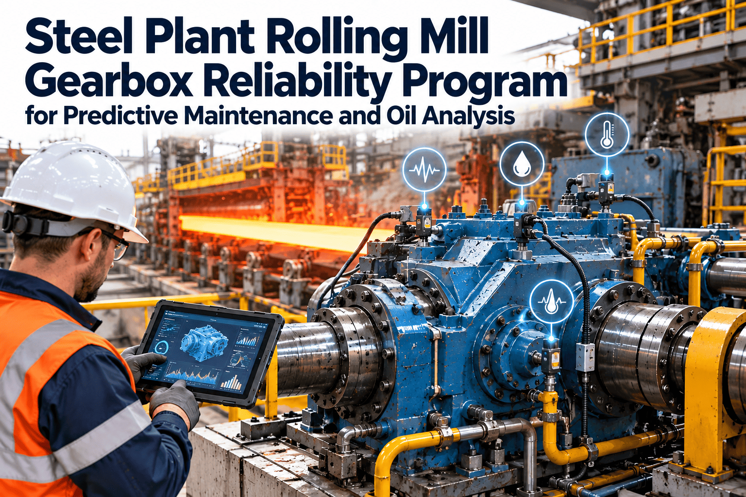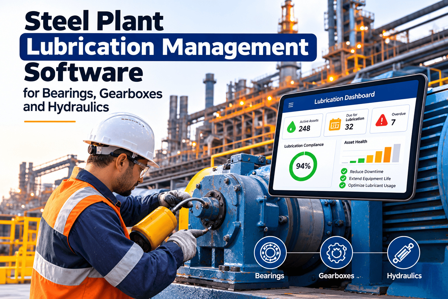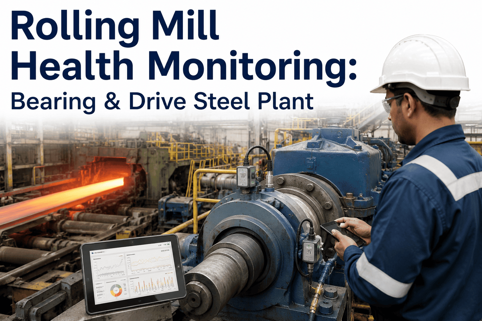
Rolling mill lubrication failure prevention begins with an uncomfortable fact: most bearing and gearbox damage in a mill is gradual, measurable and preventable long before a roll change, a stand outage or a rejected coil. Dirty oil, water from roll coolant, wrong viscosity, starved chocks and bypassed filters rarely trigger an alarm until the damage is already advanced. This guide shows how steel plant reliability teams control contamination, read oil analysis and turn every lubrication finding into scheduled work. It also explains how Oxmaint maintenance management software keeps lube routes, samples and filter changes on one auditable record.
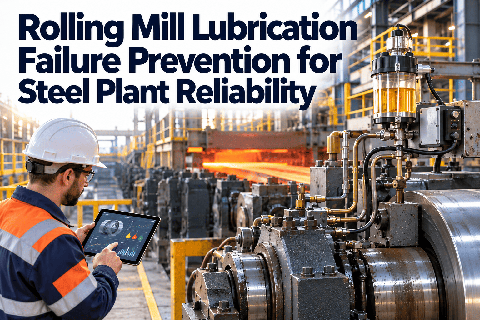
Rolling Mill Lubrication Failure Prevention for Steel Plant Reliability
Roll neck bearings, pinion stand gearboxes and hydraulic systems fail when the oil film fails. Control contamination, trend oil condition and schedule lubrication work from one maintenance system before a lube problem becomes a stand outage.
Why mill lubrication failures look sudden but are not
A rolling mill is a wet, hot, dusty and heavily loaded environment. Roll neck bearings sit beside high-pressure coolant, scale and shock loading, so the lubricant is always under attack. Failure is usually a chain of small events, and every link in that chain can be detected.
Most plants only act at stage 4 or 5. A lubrication program built on oil cleanliness and moisture control acts at stages 1 to 3.
Five contamination and supply failures to design out
Use this map when you review a failed bearing or gearbox. Each row pairs a failure source with the mill location where it typically appears and the control that stops it.
Why water is the quiet killer in roll bearings
Bearings in work and backup roll chocks run where roll coolant is sprayed constantly. Contact seals are the main defense, and when a seal lip wears or tears, water enters the chock and mixes with the lubricant.
- Water has very low viscosity, so it can reduce the lubricant film thickness inside the rolling contact.
- Research on bearing steels links water in oil to hydrogen-related cracking, micropitting and shorter rolling contact fatigue life.
- Water attracts impurities and can form sludge that restricts oil flow into the contact.
- Grease contaminated by roll coolant loses its structure, so re-lubrication alone does not repair the damage.
Seal condition, moisture testing and chock inspection belong in the same work order template, not in three separate routines.
Reading ISO 4406 cleanliness codes in practice
ISO 4406 reports particle counts per milliliter at three sizes, usually 4, 6 and 14 microns, as a three-number code such as 21/19/16. Each step up in a range number roughly doubles the particle count, so small code changes mean large contamination changes.
These codes are examples, not specifications. Set target and alarm levels from your bearing and gearbox OEM data and your own baseline.
Oil analysis tests that matter in a rolling mill
A good sample plan combines contamination tests, oil condition tests and wear debris tests. Each answers a different maintenance question.
| Test | What it shows | Typical maintenance response |
|---|---|---|
| Particle count (ISO 4406) | Cleanliness of circulating oil and filter performance | Change or upgrade filters, find the ingress source, flush if needed |
| Water content | Seal leaks, cooler leaks, condensation, emulsion carry-over | Inspect seals and coolers, dehydrate or replace oil |
| Viscosity | Oxidation, shear, wrong product or fuel and coolant dilution | Verify product, investigate temperature and contamination |
| Acid number | Oil aging and additive depletion | Schedule oil change, check cooler and temperature control |
| Elemental spectroscopy | Wear metals, additives and external contaminants | Compare to baseline and trigger inspection of the wearing component |
| Ferrography or debris analysis | Shape and size of wear particles | Decide between monitoring, borescope inspection and planned repair |
Trend every result against the same asset and the same sampling point. A single reading is a snapshot, while a trend is a prediction.
Mill lubrication points and what to watch
Assign each lube point to a named asset in the maintenance system so history follows the component, not the person who happened to take the sample.
| Lube point | Common failure signal | Work order trigger |
|---|---|---|
| Roll neck oil film bearings | Rising bearing temperature, water in oil, oil film pressure drift | Moisture limit exceeded or pressure outside range |
| Work and backup roll chocks | Grease washout, seal damage, missed re-lube | Interval overdue or seal inspection fail |
| Pinion stand and main gearboxes | Wear metals, gear mesh noise, filter differential pressure | Iron trend rising or filter alarm |
| Spindles and couplings | Dry grease points, fretting, backlash growth | Lube route finding or vibration change |
| Hydraulic AGC and servo valves | Slow response, valve sticking, fine particle contamination | Cleanliness code above target |
| Main drive motor bearings | Grease degradation, rising temperature | Temperature trend or overdue grease task |
Put every lube point on a schedule your team can prove
Create lubrication routes, sample tasks and filter changes in Oxmaint and see what is overdue before it becomes a failure.
Reactive lubrication versus condition-based lubrication
The biggest gain is not a new sensor. It is replacing fixed habits with decisions based on oil and equipment condition.
Reactive habit
- Grease and oil changes on a calendar nobody revisits
- Samples taken irregularly, results filed in email
- Filters changed after a bypass alarm or a failure
- Top-up oil drawn from shared containers
- Failure analysis stops at "bearing failed"
Condition-based practice
- Intervals adjusted from temperature, load and oil results
- Fixed sampling schedule with results trended per asset
- Filters changed on differential pressure and cleanliness data
- Dedicated, labeled containers per lubricant type
- Root cause recorded and linked to the asset history
Lubrication route checklist by frequency
Use these lists as the starting point for recurring work orders and adjust them to your mill design and OEM manuals.
Every shift
- Reservoir level and oil appearance
- Supply pressure and return temperature
- Filter differential pressure indicators
- Visible leaks at seals and fittings
- Grease pump and distributor operation
Weekly or monthly
- Collect oil samples from the same port
- Inspect breathers and desiccant condition
- Check chock seals for coolant ingress
- Verify lube point labels and containers
- Review overdue lubrication tasks
At roll change or shutdown
- Replace seals showing wear or damage
- Flush systems after component repair
- Clean coolers and verify heat transfer
- Test pressure switches and relief valves
- Record findings against each asset
Filtration, breathers and top-up practice
Filtration is the cheapest place to win cleanliness, because it works on every liter of oil that circulates through the mill, every shift.
- Fit desiccant breathers on reservoirs and gearboxes so humid mill air cannot carry moisture and dust into the oil.
- Pre-filter new oil through a transfer cart before it enters a reservoir, since drum oil is not automatically clean.
- Track filter differential pressure and replace elements by condition, not only by calendar date.
- Use offline kidney-loop filtration on large reservoirs where the main filters cannot keep up with ingress.
- Seal fill ports with quick-connect fittings so open buckets and funnels stop being a contamination route.
Each of these items becomes a recurring task or inspection point in the maintenance system, with a named owner.
Planning lubrication work around roll changes
Roll changes and planned outages are the best window to fix seals, replace filters and flush systems, because the equipment is already accessible.
Before the outage
- Review open lubrication findings and sample trends
- Reserve seals, filter elements and lubricants
- Release planned work orders with instructions
After the outage
- Take a first sample to confirm cleanliness after repair
- Close work orders with findings and photos
- Update intervals if the inspection changed the picture
Common lubrication program mistakes
These patterns show up repeatedly when teams review lubrication related failures.
- Adding more grease to compensate for a failed seal instead of repairing the seal.
- Taking samples from drain valves or the bottom of the tank rather than a consistent live-zone port.
- Setting alarm limits once and never updating them as baselines change.
- Keeping oil analysis reports in a lab portal that maintenance planners never open.
- Treating lubrication tasks as low priority and deferring them when the schedule is tight.
- Mixing greases with incompatible thickeners during a hurried top-up, which can soften the grease and let it wash out of the chock.
- Ignoring the cooler until oil temperature alarms, even though fouling raises temperature slowly and quietly for months.
KPIs that show whether lubrication control is working
Pick a small set and review it monthly with maintenance and operations.
How Oxmaint supports a mill lubrication program
Oxmaint works as the system of record that connects lubrication tasks, asset history and corrective work.
- Build the asset register. Add stands, chocks, gearboxes and hydraulic units, with each lube point as a child asset.
- Schedule preventive maintenance. Create recurring lube routes, sampling tasks and cooler cleaning with clear instructions.
- Use mobile inspections. Technicians record readings, findings and photos from the mill floor.
- Set condition triggers. Out-of-range results, such as high water or poor cleanliness, create corrective work orders.
- Manage lubricants and filters. Track filter elements, seals and lubricants in inventory so parts are ready for planned jobs.
- Report and review. Dashboards show overdue tasks, repeat failures and cost by asset for planning meetings.
Closing the loop with root cause records
A failed bearing is only useful if the lesson stays with the asset. Record the same fields every time.
- Which lubricant, which interval and which seal were in service
- Last oil analysis result and the trend before failure
- Whether the alarm, route or sample plan would have caught it
- The corrective action and the task that now prevents repeat
This turns each failure into a change in the preventive maintenance plan instead of a one-time repair.
Rolling mill lubrication FAQs
What causes most rolling mill bearing lubrication failures?
Common causes are water or coolant ingress, particle contamination, missed re-lubrication and the wrong lubricant. Most can be caught by sampling and seal inspection.
How often should mill gearbox oil be sampled?
Set the interval from criticality and operating conditions, then tighten it when trends move. You can schedule every sample in Oxmaint.
What ISO 4406 code should we target?
Use your bearing or gearbox OEM requirement, then set alarms from your own baseline. Cleaner targets suit critical bearings and hydraulic servo systems.
Can a CMMS replace an oil analysis lab?
No. The lab produces the data, while the CMMS schedules sampling, records results and triggers work. A short demo shows the workflow.
How do we prove lubrication compliance to auditors?
Keep completed lube tasks, sample results and corrective actions linked to each asset. Date-stamped work order history acts as the evidence trail.
Stop treating lubrication as a background task
Give your mill team one place to plan lube routes, trend oil condition and close out corrective work. Start now or see it on your own mill assets.