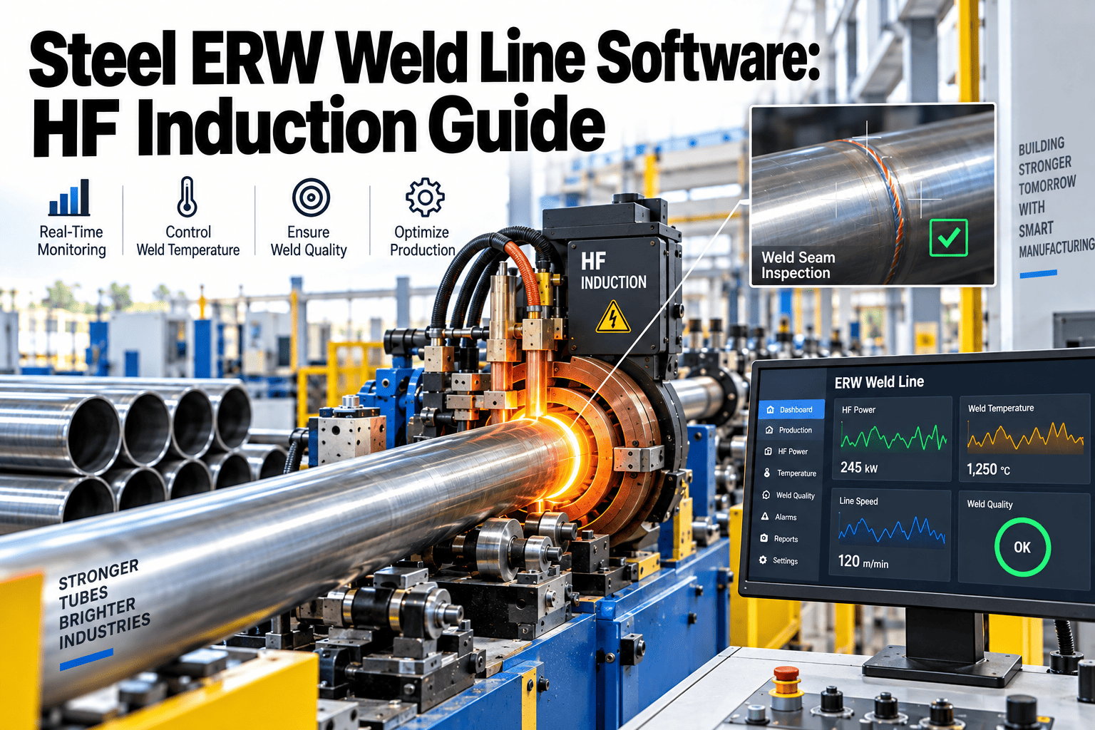
An ERW weld line has no margin for drift. The strip edges are heated to forging temperature in a fraction of a second, squeezed together by rolls turning at line speed, and the seam is gone from view within seconds — buried under scarfing debris and a coating of scale. If the high-frequency power, the squeeze pressure, or the roll alignment is off by a small amount, the defect rides inside the pipe wall until a hydrostatic test, an in-service failure, or an API audit finds it. That is why ERW weld line software exists: to keep the process parameters that determine seam integrity — and the maintenance condition of the equipment that controls them — inside a documented, auditable band on every foot of pipe produced, whether the product is line pipe, OCTG casing, or structural tube.
HF induction ERW weld quality has three variables. Miss one and the seam fails.
HF power, squeeze roll pressure, and weld line offset interact in real time to forge the longitudinal seam on every ERW pipe. A CMMS built around this process turns coil, impeder, and squeeze-roll condition into a controlled input instead of a hidden variable.
Tube mill failure modes show up as product defects, not breakdowns
On most rolling equipment, a worn bearing eventually causes a stoppage — an event that is visible, logged, and repaired. On an ERW weld line, the same worn bearing can keep running for weeks while quietly shifting squeeze pressure, and the only evidence is a slowly rising reject rate or, worse, a seam that passes in-line inspection but fails months later in service.
That is the planning gap a generic CMMS built for rotating equipment rarely closes, and it is the reason tube and pipe mills increasingly ask for maintenance software that understands the weld box as a process-critical system rather than a maintenance line item.
Three variables decide whether the seam holds or fails downstream
ERW pipe carries no filler metal. The strip edges themselves are heated to a plastic, near-melting state and forged together mechanically — which means every input into that forging event is a direct input into weld strength.
HF induction power & heat-input factor
Welding power divided by line speed sets the heat-input factor. Too low, and the weld is "cold" — unfused edges that pass a visual check but fail hydrostatic or in-service pressure. Too high, and the heat-affected zone widens, dropping toughness and Charpy impact values below API grade requirements.
Squeeze roll pressure & upset
The squeeze rolls forge the heated edges together and expel oxides and molten material as an upset bead. Worn roll bearings, misaligned roll stands, or pressure drift change the upset profile — and an inconsistent upset is one of the most common root causes of cold-weld rejects at hydrostatic test.
Weld line offset & forming alignment
If the forming rolls upstream of the weld box do not deliver the strip edges into the induction coil on a true, repeatable line, the weld point wanders. Offset seams concentrate stress at the ID and OD, and are a leading cause of scrap that cannot be reworked — only cut out.
Where weld quality is won or lost on the ERW line
Eight stations turn flat coil into finished pipe. Weld quality is set almost entirely across three of them — welding, forging, and scarfing — but every upstream station affects how the strip arrives at the weld point.
Uncoiling & edge trim
Hot or cold rolled coil is uncoiled and strip edges are trimmed to a consistent width — the starting point for weld line offset control.
Progressive roll forming
A series of forming rolls curls the flat strip into an open tube, bringing the two edges toward each other at a controlled V-angle ahead of the weld box.
HF induction welding
A high-frequency coil and impeder concentrate current on the strip edges, heating a narrow zone to forging temperature in milliseconds.
Squeeze roll forging
Squeeze rolls close the vee and forge the heated edges into a homogeneous seam, expelling contaminants as an upset bead inside and out.
Seam scarfing
Cutting tools remove the internal and external upset bead flush with the pipe surface — a worn or misaligned scarfing tool leaves flash or gouges the base metal.
Seam normalizing
Induction post-weld heat treatment refines the heat-affected zone grain structure, restoring toughness lost to the welding thermal cycle.
Sizing & straightening
Final rolls bring the pipe to OD tolerance and straightness — misalignment here can reintroduce seam stress that the forging stage removed.
In-line NDT & hydrostatic test
On-line ultrasonic or eddy current scanning covers 100% of the seam, followed by hydrostatic or API-specified testing before cut-to-length.
The weld box parameters an ERW CMMS should never lose track of
Weld quality data is often trapped in the welder's PLC trend screen and never connected to the maintenance record of the equipment producing it. Closing that gap is the difference between a documented process and a guess.
| Parameter | Typical Target Range | Consequence of Drift | Maintenance Link |
|---|---|---|---|
| HF welder power / line speed ratio | Heat-input factor held within WPS-qualified band | Cold weld (under) or wide HAZ, low toughness (over) | Generator calibration, coil wear PM |
| Squeeze roll pressure | Set per wall thickness and grade schedule | Incomplete forging, inconsistent upset bead | Roll bearing vibration, hydraulic set-point check |
| Weld line offset | Within forming-mill alignment tolerance | Seam wander, ID/OD stress concentration | Forming roll alignment, guide wear inspection |
| Impeder condition | Ferrite intact, cooling water flow stable | Weld current losses, unstable heat-input | Scheduled impeder replacement interval |
| Scarfing tool edge | Sharp, correctly set to bead height | Residual flash or base-metal gouging | Tool-change PM tied to footage counter |
How a small squeeze-pressure drift becomes a seven-figure liability
Consider an OCTG mill producing 13-3/8 inch casing where squeeze roll bearing wear allows forging pressure to fall 8% below the qualified WPS setting over a single shift.
We were tracking weld PLC alarms and squeeze roll bearing condition in two different systems. By the time maintenance saw the vibration trend, three shifts of pipe were already downstream of the weld box.
What API 5L, API 5CT, and ASTM A53 expect from an ERW seam
The specification a mill is qualifying against changes how tightly the weld box parameters must be controlled — and how much documentation a quality department needs on hand when an auditor or customer asks for it.
Line pipe, PSL1 and PSL2
Covers ERW line pipe from low-pressure gathering service up through sour-service-rated grades. PSL2 requires full-body ultrasonic testing, tighter chemistry control, and documented Charpy impact testing on the weld seam and heat-affected zone.
OCTG casing & tubing
Downhole service adds collapse, burst, and tension load cases the seam must survive over the well's life. Weld joint factor and normalizing effectiveness are scrutinized more closely than on structural-grade ERW production.
Structural & mechanical tube
A more permissive weld joint factor than full API 5L testing, but still requires consistent hydrostatic or eddy current screening — and a mill that under-controls the weld box here risks losing the margin that made the lighter spec viable.
Across all three, the common thread is traceability: an auditor does not just want to see a passing hydrostatic test result, they want to see that the equipment producing the seam was in a known, maintained condition at the time the pipe was made. That is the record an ERW-specific CMMS is built to produce — linking asset condition history directly to the production lot, so a compliance answer is a query instead of a week-long log search across the weld PLC, the maintenance shift log, and the NDT report. When a customer or third-party inspector asks for the maintenance history behind a specific heat number or lot range, a searchable, timestamped record shortens that review from days to minutes and removes the guesswork from what would otherwise be a manual reconstruction of shift logs, work orders, and calibration sheets.
Connect weld box condition to weld quality — before the next coil runs.
See how a maintenance platform built for ERW tube and pipe mills links squeeze roll, impeder, and coil condition to your seam quality record.
How Oxmaint keeps the weld box inside its qualified window
Oxmaint does not replace the weld monitoring system on the mill — it manages the equipment condition that keeps that system's readings trustworthy, and ties every reading back to a traceable maintenance record.
Weld box asset hierarchy
HF generator, induction coil, impeder, and squeeze roll stands are modeled as linked assets, so a footage-based wear trigger on one component is visible against the others.
Footage- and time-based PM scheduling
Squeeze roll bearing inspection, impeder replacement, and scarfing tool changeout are scheduled against production footage counters, not just calendar intervals.
Mobile weld-box inspection checklists
Operators and technicians run standardized mobile checklists for roll alignment, coolant flow, and generator readings at shift handover, with photo evidence attached to the asset record.
Corrective work order triage
A vibration or pressure deviation flagged during inspection generates a prioritized work order automatically, routed to the right crew before the next coil change.
Critical spares tracking
Impeders, ferrite cores, squeeze roll bearings, and scarfing blades are tracked against consumption rate so a stockout never becomes the reason for deferring a required PM.
API 5L / API 5CT traceability records
Maintenance history for the weld box is retained against the production lot, giving quality and audit teams a defensible link between equipment condition and released pipe.
Spreadsheet-tracked weld box vs. a connected CMMS
- Squeeze roll and impeder history lives in separate logs from weld PLC data
- PM intervals are calendar-based, disconnected from production footage
- Root-cause investigation after a reject means manually cross-referencing shift logs
- Spares reordering is reactive, based on whoever notices the bin is empty
- Weld box asset condition and inspection data sit in one traceable record
- PM triggers combine footage counters with condition thresholds
- Deviation-to-defect correlation is queryable in minutes, not days
- Spares consumption drives automatic reorder points for critical wear parts
ERW HF induction weld line maintenance — answered
What is the difference between HF-ERW and older LF-ERW pipe?
HF-ERW uses a 100–400 kHz current to concentrate heat narrowly at the strip edges, producing a tighter heat-affected zone than the older low-frequency process. API 5L now requires HF welding for all ERW line pipe production.
Why does squeeze roll condition matter more than the HF generator setting alone?
Heat and forging pressure act together during the weld. A correctly heated edge that is not forged with sufficient, consistent pressure still produces a weak or cold weld, which is why squeeze roll bearing and alignment condition is tracked as a weld-quality input, not just an uptime metric.
Can Oxmaint connect to our existing weld monitoring or PLC system?
Oxmaint is built to sit alongside your process control and NDT systems, capturing the maintenance and inspection side of weld box condition. Schedule a Demo to review your specific weld monitoring setup.
How does post-weld normalizing fit into the maintenance picture?
The in-line seam normalizer is itself a maintained asset — induction coil wear or temperature control drift on the normalizer can leave the heat-affected zone under-treated even when the initial weld was sound, so it belongs in the same PM schedule as the weld box.
How quickly can a mill get weld box assets into Oxmaint?
Most ERW mills have core weld box assets — generator, coil, impeder, squeeze stands, scarfing tools — modeled and on a PM schedule within the first two to three weeks. Get Started to begin your setup.
Put every ERW weld box asset on a documented, footage-driven maintenance record
Tube and pipe mills running OCTG and structural ERW production use Oxmaint to connect squeeze roll, impeder, and coil condition to seam quality — not spreadsheets.
Free trial · No credit card