Every girth weld on a steel pipe spool is decided before the arc is ever struck. Bevel angle, root face, fit-up gap, and hi-lo offset set the geometry the root pass has to fill — and once a welder tacks a joint with the wrong gap or an uncorrected hi-lo, no amount of skill downstream fully removes the risk of incomplete fusion or root suck-back. Alignment discipline is the least glamorous part of pipe fabrication and the most repeated cause of weld repair. This guide covers the four measurements that decide weld quality, the root causes behind most fit-up defects, the KPIs a fabrication shop should track, and how weld alignment software turns a tape-measure-and-memory process into a documented, traceable one that quality teams can actually stand behind at audit.
A weld is only as good as the fit-up it started from
Bevel angle, root gap, land thickness, and hi-lo offset are measured, adjusted, and re-checked before a single weld pass — and each one has a documented tolerance a welding procedure specification requires you to hold.
What "alignment" actually means at the joint
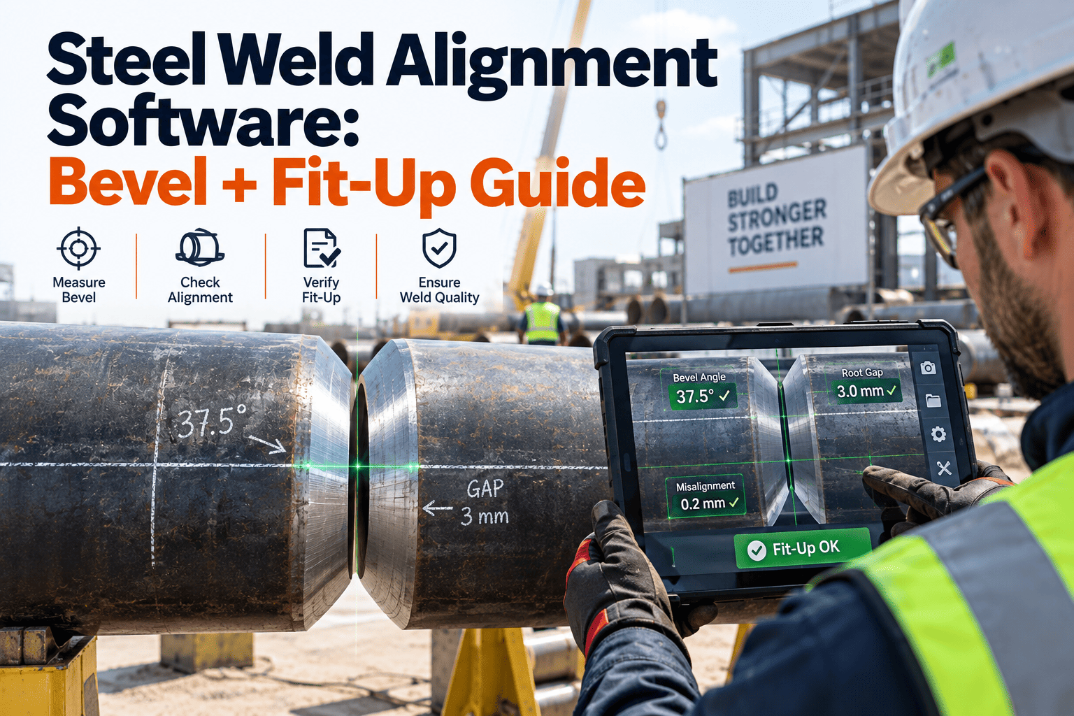
Fit-up is not one measurement — it is four, checked at multiple points around the circumference before a tack is made and again after tacking, because tacking itself can pull a joint out of tolerance.
Bevel angle
The machined or ground angle on each pipe end, typically 37.5° per side for a 75° included V-groove, controlling root access and weld metal volume.
Root face (land)
The flat, unbeveled thickness left at the pipe edge — commonly 1.6 mm ± 0.8 mm — that limits burn-through risk on the root pass.
Root gap
The space between the two root faces once the pipes are pulled together — usually 1.6 to 3.2 mm, set by the qualified welding procedure specification.
Hi-lo offset
The mismatch in wall thickness or internal diameter across the joint. Left uncorrected it concentrates stress at the root and is a leading cause of premature girth weld failure.
Where alignment checks belong in the joint workflow
Fit-up is not a single inspection point — it is a sequence of checks, each of which can be undone by the step that follows it if it goes unrecorded.
Pipe receiving verification
Incoming wall thickness, OD, and ovality are checked against the mill certificate before the joint is scheduled, catching lot-to-lot tolerance mismatches early.
Beveling & edge prep
Bevel angle and root face are cut and gauge-checked at the machine, before the pipe ever reaches the fit-up stand.
Clamping & gap setting
Internal or external line-up clamps pull the joint into round and set the root gap, with hi-lo verified at multiple points around the circumference.
Tack & post-tack re-check
Tack welds can shrink and pull the joint — a re-check after tacking, before the clamp is released, is what actually protects the root gap through the root pass.
Skipping the post-tack re-check is one of the most common gaps on a busy shop floor, because the clamp is needed for the next joint and the pressure to move on is constant. Recording that step as a required, timestamped field in the joint record — rather than an assumed best practice — is what keeps it from being the one check that quietly disappears under schedule pressure, and it gives the crew coming in on the next shift a clear, verifiable starting point rather than a joint they simply have to trust was checked.
Alignment discipline across pipe, structural, and vessel work
Girth welds under pressure cycling
Hi-lo and root gap control directly govern fatigue life at girth welds subject to repeated pressure and thermal cycling, making fit-up tolerance one of the tightest in this segment.
Column and beam splice joints
Angular misalignment at a splice joint changes the load path through the member, so alignment tolerance is checked against structural design drawings as well as the WPS.
Shell course and head-to-shell joints
ASME code work often carries the tightest hi-lo tolerances of any application, since vessel joints are radiographed at a much higher acceptance standard than general piping.
Root causes of poor fit-up on the shop floor
Bevel machines running past their edge-wear life
A beveling tool or plasma bevel head with worn cutting edges drifts off the specified angle gradually — the pipe looks correctly beveled to the eye long before a bevel gauge would catch the deviation.
Line-up clamps not recalibrated between diameter changes
Internal and external line-up clamps hold the joint's roundness during tacking. A clamp that has not been checked after a large run of a different pipe schedule can force a false roundness that reopens as hi-lo once released.
Wall thickness and ovality drift from upstream mill tolerance
Pipe that is within mill tolerance individually can still produce a hi-lo mismatch when two lots with opposite-end tolerances are joined — a condition only caught by measuring the actual joint, not trusting the certified mill sheet.
Fit-up gauges lost, uncalibrated, or unavailable at the joint
Hi-lo and bevel gauges are small, shared tools. When the one calibrated gauge is on the other side of the shop, welders fit up by eye and trust the tack — the single most common informal deviation from procedure.
Fit-up tolerance ranges by joint parameter
Exact tolerances always come from the qualified welding procedure specification and governing code — the ranges below are the typical bands a fit-up inspection checks against before a tack is approved, and they should be treated as a starting reference rather than a substitute for the project's own qualified WPS values.
| Parameter | Typical Range | Checked With | Risk if Out of Tolerance |
|---|---|---|---|
| Bevel angle | 37.5° ± 2.5° per side (single V) | Bevel protractor / gauge | Poor root penetration or excess weld metal fill |
| Root face (land) | 1.6 mm ± 0.8 mm | Hi-lo / bevel gauge | Burn-through if too thin, lack of fusion if too thick |
| Root gap | 1.6–3.2 mm, per WPS | Feeler gauge, wire gauge | Excess gap causes burn-through; tight gap causes lack of fusion |
| Hi-lo (internal misalignment) | 1.5–3 mm typical piping limit | Hi-lo gauge, internal line-up clamp indicator | Root stress concentration, premature fatigue failure |
| Angular misalignment | Per code; commonly under 3° total | Straight edge, laser alignment tool | Bending stress at the joint under service load |
A joint fitted by eye vs. a joint fitted to a documented check
- Hi-lo estimated visually or with a shared, uncalibrated gauge
- No record of which bevel machine or clamp produced the joint
- Root cause of a weld repair traced back through memory and guesswork
- Repeat offenders in fit-up defects go unnoticed across shifts
- Bevel angle, root gap, and hi-lo logged against the joint ID before tack
- Bevel machine and clamp asset ID linked to every fit-up record
- A defect trend map points straight to the machine or shift causing it
- Gauge calibration status is checked automatically before sign-off
How a 2.5 mm hi-lo becomes a full joint cut-out
A structural steel fabricator running large-diameter process piping tacked a joint with a hi-lo of roughly 2.5 mm — inside what the welder judged acceptable by eye, but never measured against the WPS limit of 1.5 mm for the service class.
This pattern repeats across most fit-up-related weld repairs: the defect is expensive not because the geometry was dramatically wrong, but because it was small enough to pass an unrecorded visual check while still being outside the qualified tolerance. A single mandatory gauge reading, logged against the joint before the tack is approved, closes that gap without adding meaningful time to the fit-up step itself.
KPIs that show whether fit-up discipline is actually working
A fit-up program is only as good as the metrics a plant tracks against it. These are the indicators that separate a documented process from a program that exists only on paper.
First-pass fit-up acceptance rate
The share of joints that pass fit-up inspection without a re-fit. A falling rate on a specific line, crew, or pipe schedule is usually the earliest signal of a tooling or training issue.
NDT rejection rate tied to root defects
Root concavity, incomplete fusion, and burn-through findings correlated back to the fit-up record show whether alignment control is actually reducing downstream weld repair.
Gauge calibration compliance
The percentage of fit-up checks performed with a currently calibrated gauge, verifiable against the tool's own maintenance record rather than a sign-off sheet.
Time from fit-up rejection to rework
How long a rejected joint sits before it is re-fit and re-tacked — a widening gap here is usually a scheduling or communication problem more than a skills problem.
Turn fit-up inspection into a recorded step, not a judgment call.
See how steel fabrication teams log bevel, gap, and hi-lo checks against every joint before a tack is approved.
How Oxmaint supports weld alignment discipline
Oxmaint does not replace the welder's gauge or the inspector's judgment — it makes sure the check happens, is recorded against the right joint and asset, and is visible before the next process step starts.
Mobile fit-up checklists
Bevel angle, root gap, root face, and hi-lo fields are built into a mobile inspection form tied to the joint or spool ID, with photo evidence attached before tack sign-off.
Bevel machine & clamp tracking
Every bevel head, plasma cutter, and internal or external line-up clamp is a tracked asset, so recurring fit-up defects can be traced to a specific tool's wear or calibration state.
Gauge calibration scheduling
Hi-lo gauges, bevel protractors, and feeler gauge sets are scheduled for recalibration on a defined interval, with overdue tools automatically flagged before use.
Rejection-to-rework routing
A fit-up that fails inspection generates a corrective work order automatically, routed to the fabrication crew responsible, instead of relying on a verbal handoff.
WPS-linked joint records
Fit-up data is stored against the joint and the governing WPS revision, giving QA a defensible, searchable record instead of a paper traveler that can go missing.
Fit-up defect trend view
Rejection rates roll up by shift, crew, bevel machine, and pipe schedule, surfacing recurring root causes that a single-joint view would never reveal.
Steel weld alignment and fit-up — answered
What is the difference between hi-lo and angular misalignment?
Hi-lo is a radial or wall-thickness offset across the joint circumference, while angular misalignment is a bending angle between the two pipe centerlines. Both concentrate stress at the root but are measured with different tools and corrected using different clamp or wedge adjustments before the tack is made.
Why is root face thickness controlled so tightly?
The root face governs how much material the root pass has to fully fuse without burning through. A land that is too thick leaves incomplete fusion risk; too thin risks burn-through, especially on open-root welds without backing.
Can fit-up data be tied to a specific welding procedure specification?
Yes — fit-up checklists can be configured against the tolerance bands of the governing WPS, so an inspector is checking against the qualified range for that joint rather than a generic default. Schedule a Demo to see a sample configuration.
How does gauge calibration tie into fit-up quality?
A hi-lo or bevel gauge that has drifted out of calibration can pass a joint that is actually out of tolerance without anyone knowing until a weld fails inspection much later. Scheduling and flagging gauge calibration is treated as part of the fit-up control loop, not a separate metrology task handled by a different department on a different schedule.
How fast can a fabrication shop start logging fit-up checks?
Most shops configure a mobile fit-up checklist and get crews logging joints within the first week. Get Started to set up your first inspection form.
Make bevel, gap, and hi-lo checks a recorded step before every tack
Steel fabrication teams use Oxmaint to turn fit-up inspection into a documented, traceable part of the weld record.
Free trial · No credit card