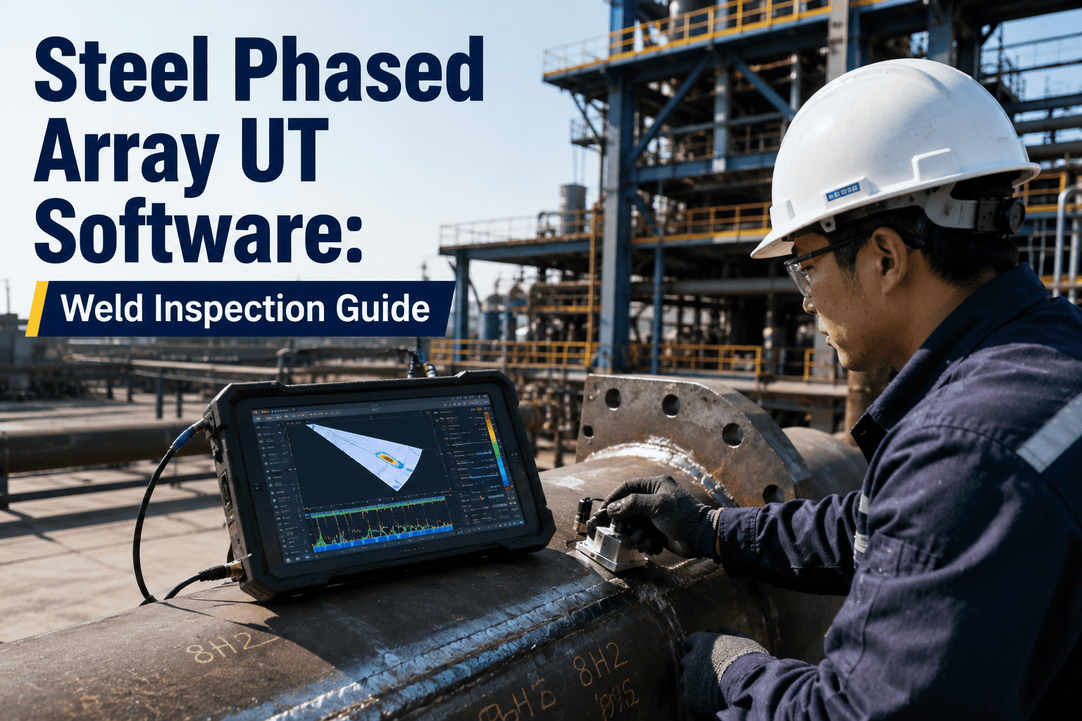
Radiography built the last fifty years of weld quality control in steel plants, but it comes with shielded enclosures, exposure permits, and film that takes hours to develop before a fabrication crew even learns whether a joint passed. Phased array ultrasonic testing turns that wait into minutes: a probe sweeps a beam electronically through the weld, builds a cross-sectional image in real time, and sizes a flaw against a calibrated DAC curve on the same screen. For plate mills, pipe mills, structural fabrication shops, and pressure vessel shops running dozens of welds a shift, that difference decides whether inspection is a bottleneck or a checkpoint. The catch is that PAUT is only as reliable as the calibration, DAC curve, and encoder discipline behind every scan — and most shops still track that discipline on paper logs, loose spreadsheets, and a technician's personal notes that nobody can audit six months later when a customer or code body asks for proof. See how a connected CMMS keeps every PAUT calibration record audit-ready before your next code inspection.
Phased Array UT Software for Steel Weld Inspection
PAUT has replaced radiographic testing as the default volumetric method for production weld inspection across plate mills, pipe mills, structural steel shops, and pressure vessel fabricators. It reads a full cross-section of a weld in seconds using a single encoded probe sweep, sizes defects against a calibrated DAC or TCG curve, and produces a digital S-scan record instead of a film that needs a darkroom and a trained radiographer to interpret. The technology itself is proven and code-accepted in nearly every heavy-fabrication standard written in the last decade. What actually separates a mill that gets consistent, code-compliant results from one that gets rejected reports is far less glamorous — it is how calibration blocks, DAC curves, encoder checks, and scan files are tracked between shifts, technicians, and projects.
RT vs Conventional UT vs Phased Array UT
Steel fabrication and pressure equipment codes now accept PAUT as an equal or preferred alternative to radiography in most weld categories, and many customer specifications have started requiring it outright for thick-section and high-volume joints. The table below compares the three volumetric methods a QC department typically chooses between on a structural or pressure weld, from result speed to the standards each one has to satisfy.
| Factor | Radiographic Testing | Conventional UT | Phased Array UT |
|---|---|---|---|
| Result availability | Hours — film processing and viewing | Minutes — single-angle A-scan only | Seconds — live cross-sectional S-scan |
| Safety controls needed | Radiation zone, exposure badges, permits | None | None |
| Flaw sizing method | Density comparison against film | Manual amplitude drop, single beam angle | DAC/TCG curve against calibrated reflector, multi-angle S-scan |
| Record format | Physical film, degrades over time | Handwritten chart, limited traceability | Digital file — replayable, exportable, archivable |
| Governing references | ASME Section V Article 2 | ISO 17640 conventional levels | ISO 13588, ISO 17640, ISO 19285, ASME Section V Article 4 |
| Best fit | Thick-section, low-volume shops | Spot checks, simple geometry | Production welding, thin-to-thick range, high joint volume |
How a Compliant PAUT Scan Actually Runs
A phased array reading is only trustworthy if six steps happen in order, every time, on every joint. Skipping the calibration step, rushing the encoder check, or reusing an old DAC curve on a different plate thickness is the single most common reason a PAUT report gets thrown out during a code audit, and it is almost always a paperwork failure rather than an equipment failure.
Common Weld Defects and Their PAUT Signature
Every flaw type produces a different pattern on an S-scan, and experienced technicians learn to read the shape, amplitude behavior, and angular response almost as quickly as a radiographer reads film density. Knowing what to expect at each angle speeds up disposition, reduces rework from over-calling geometric reflectors, and keeps the report defensible if a customer's third-party inspector wants to review the same data later.
What Every Calibration File Needs to Hold Up in Audit
Most rejected PAUT reports are not rejected because the flaw call was wrong — they are rejected because the calibration behind the call cannot be verified. A complete calibration file should answer six questions on its own, without anyone needing to ask the technician who ran the scan.
Where a Steel CMMS Fits Around the PAUT Scan
Oxmaint does not replace the phased array instrument — it wraps the paperwork, traceability, and asset history around it, so scan data stops living on a technician's laptop or a personal USB drive and starts living against the weld, the joint, and the equipment record it belongs to. That shift matters most on the day a customer, a code inspector, or an insurance auditor asks for a record from a weld made eighteen months ago.
What Changes When PAUT Records Move Off Paper
Shops that digitize their PAUT calibration and disposition records tend to describe the same four shifts, regardless of whether they run structural steel, pipe, or pressure vessels.
Standards Quick Reference for Steel Weld PAUT
A written PAUT procedure should point to the exact standard governing testing level, acceptance criteria, and calibration method for the product being welded. This quick reference covers the standards most often cited in steel mill and fabrication shop procedures.
| Standard | Scope | Relevance to PAUT |
|---|---|---|
| ISO 17640 | Ultrasonic testing levels for welds | Reference block, calibration distance, and DAC curve requirements PAUT must equal or exceed |
| ISO 13588 | Mechanized PAUT procedure | Base procedure structure for phased array setup and qualification |
| ISO 19285 | PAUT acceptance levels | Defines acceptance criteria specific to phased array indications |
| ASME Section V, Art. 4 | Ultrasonic examination | Accepts PAUT as an alternative to radiography for pressure equipment welds |
| ASTM E-1961 | Girth weld zonal discrimination | Zone-based scanning practice widely used for pipeline and pipe mill welds |
| AWS D1.1 Annex S | Structural UT procedure | PAUT qualification pathway for structural steel welds |