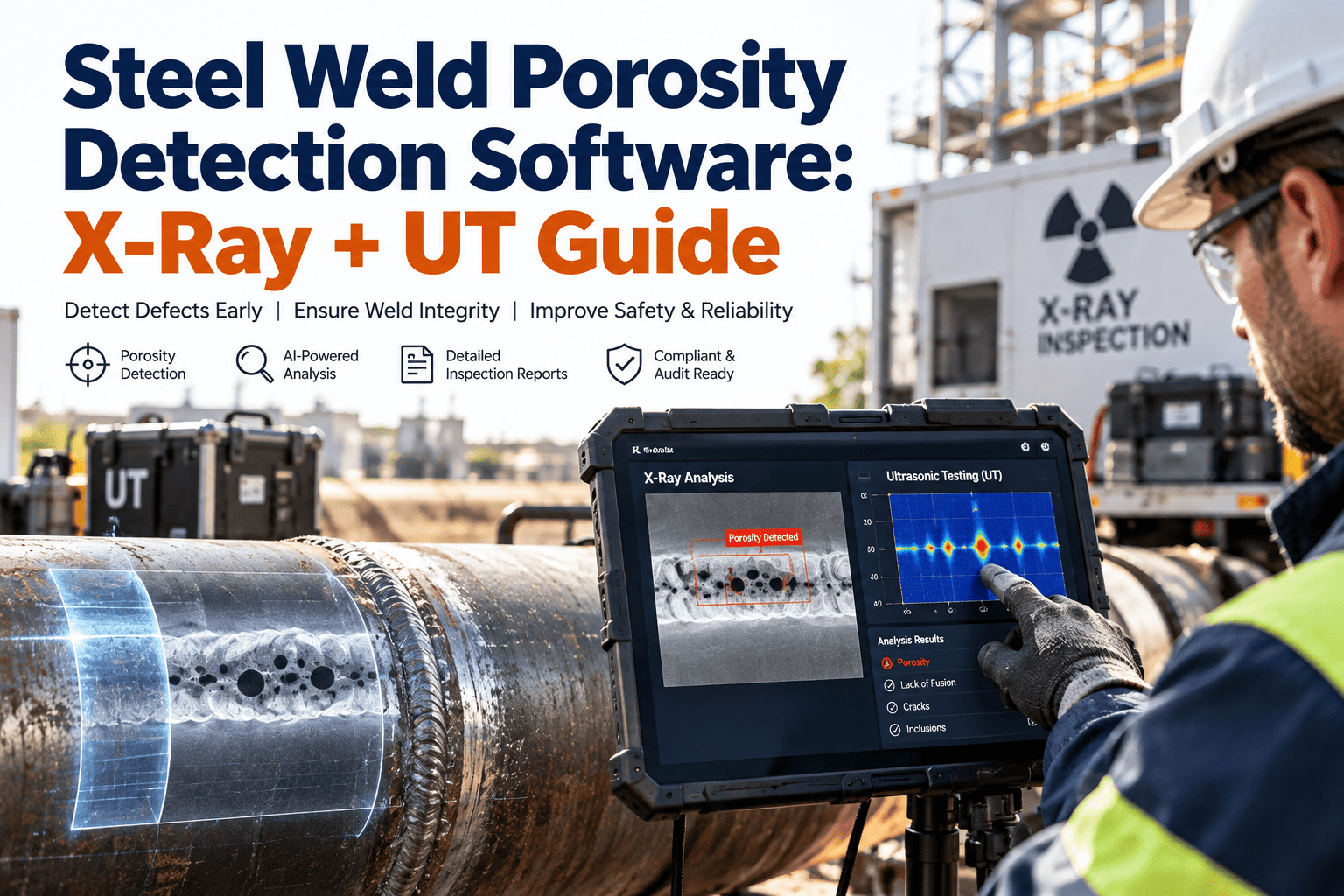
Weld porosity is the single most common rejection cause on steel pipe and plate fabrication lines, and it rarely announces itself until an X-ray film or a phased array scan catches a cluster of gas pockets buried in the fusion zone. For QA teams running mixed X-ray and ultrasonic testing programs, the real challenge isn't finding porosity — it's connecting inspection results to root cause fast enough to stop a shift from producing the same defect a hundred more times. This guide covers how steel plants classify, trace, and prevent weld porosity using a CMMS-driven inspection stack, and how acceptance criteria under codes like AWS D1.1 and API 1104 shape what actually gets rejected versus repaired, since not every gas pocket that shows up on film is automatically a failed joint.
Porosity found on film is porosity that already shipped past the welder
Radiographic and phased array ultrasonic testing catch porosity after the weld is complete. OxMaint closes the loop by tying every reject back to the welder, the procedure, and the consumable lot — so the next joint doesn't repeat the defect. Most plants already have the inspection coverage; what's missing is the connective record that turns a rejected film into a fixed process.
The four root causes behind most steel weld porosity rejects
Porosity forms when gas is trapped in the weld pool before it solidifies. On a steel fabrication or pipe mill floor, the gas source is almost always one of four things — and each one leaves a different trace in your maintenance and consumable records. Distinguishing between them on the shop floor, rather than treating every porosity reject as a single undifferentiated category, is what separates a plant that fixes the defect from one that just reworks it and waits for the next occurrence. A reject log that captures which of these four categories applies, joint by joint, is worth far more than a raw reject count on its own.
Shielding gas contamination
Moisture in the gas line, a cracked hose, or a low cylinder pressure lets atmospheric nitrogen and oxygen into the arc. This shows up as scattered fine porosity across a joint rather than a single cluster, and it often tracks with a specific gas manifold or regulator rather than a specific welder.
Consumable moisture pickup
Flux-cored wire or SMAW electrodes left outside a rod oven absorb humidity. Hydrogen released during welding forms porosity that clusters near the weld toe and root, and it worsens measurably with every hour a consumable sits exposed on a humid shop floor.
Joint surface contamination
Mill scale, rust, oil, or paint left on the base metal decomposes in the arc and releases gas faster than it can escape the weld pool before solidification. This cause is especially common on retrofit or field welds where surface prep is rushed.
Arc length and travel speed drift
Excessive stick-out, arc length, or travel speed shortens the gas shield's dwell time over the molten pool, letting gas escape solidification capture only partially. This is the cause most likely to trace back to an individual welder's technique or a fatigue-related shift pattern.
X-ray, phased array UT, and AI vision: choosing the right porosity detection method
Most steel fabrication QA programs run more than one inspection method depending on joint thickness, access, and code requirement. Each method has a different sensitivity profile for porosity specifically, and the choice usually comes down to how the joint will be loaded in service and what governing code applies to the fabrication. Cost and cycle time also matter at production volume — a method that's ideal for a single critical joint often isn't practical across an entire pipe mill run.
| Method | Porosity detection strength | Limitation | Typical use case |
|---|---|---|---|
| Radiographic testing (RT) | Excellent for volumetric porosity, gives a permanent film record | Slow cycle time, radiation safety zone required | Pressure vessel and pipeline girth welds |
| Phased array UT (PAUT) | Strong on cluster and linear porosity, real-time sizing | Requires trained operator interpretation, couplant sensitive | Thick-section plate and structural welds |
| Digital radiography (DR) | Same sensitivity as film RT with faster turnaround | Higher equipment cost than conventional film | High-volume pipe mill inspection lines |
| AI vision porosity classification | Fast surface-breaking porosity screening, consistent scoring | Cannot detect subsurface porosity alone | First-pass screening before RT or PAUT |
How codes classify porosity: rounded, cluster, and linear indications
Not all porosity is treated equally under welding codes. AWS D1.1 and API 1104 both distinguish between porosity types and set different size and spacing limits for each, which means an inspection program has to classify the indication correctly before deciding whether a joint is rejectable or repairable. Misclassifying a cluster as isolated porosity, or vice versa, is one of the more common sources of inconsistent accept/reject decisions between shifts.
| Porosity classification | Description | General code treatment |
|---|---|---|
| Rounded (isolated) porosity | Individual gas pockets scattered through the weld metal | Sized and counted per unit length against a frequency-of-occurrence table |
| Cluster porosity | Multiple rounded pores grouped closely together | Evaluated as a single indication with a tighter size limit than isolated porosity |
| Linear porosity | Porosity aligned along the weld axis, often tracking a joint prep line | Frequently treated more like a linear discontinuity, with stricter rejection limits |
| Piping porosity (wormhole) | Elongated gas channels extending toward the weld surface | Usually rejectable regardless of size due to the through-thickness gas path |
Matching inspection frequency to joint criticality
Not every joint on a fabrication job warrants the same level of scrutiny. Governing codes and project specifications typically set inspection frequency based on the consequence of a failure at that joint, and a mature QA program mirrors that tiering in its own scheduling rather than applying one blanket sampling rate across the whole job.
| Joint criticality tier | Typical inspection coverage | Example joint type |
|---|---|---|
| Category A — full pressure boundary | 100% RT or PAUT coverage | Pressure vessel longitudinal and circumferential seams |
| Category B — primary structural | Spot RT or PAUT, typically 10–25% of joints | Main structural steel moment connections |
| Category C — secondary structural | Visual inspection with spot UT on flagged joints | Bracing and secondary framing welds |
| Category D — non-structural | Visual inspection only | Equipment supports and miscellaneous fabrication |
Tying inspection frequency to joint category also changes how a porosity trend should be interpreted. A single rejected joint in a 100%-coverage category is routine data; the same single rejection in a 10%-sampled category is a much stronger signal that the underlying process — the welder, the equipment, or the consumable lot — needs immediate review, since it likely represents a wider population of unsampled joints with the same exposure. Widening the sample rate temporarily after a single reject in a low-coverage category is a common and effective interim response while root cause is confirmed.
Turning a porosity reject into a corrective action, not a repeat defect
A reject report that only says "porosity found, weld rejected" doesn't stop the next hundred feet of pipe from failing the same way. Every reject needs to trace back through five linked records, and skipping any one of them tends to be exactly where a repeat defect slips back through undetected until the next audit cycle catches the pattern.
Log the reject against the joint ID
Record RT film number or PAUT scan ID, joint location, and defect classification directly against the asset record for that weld.
Pull the welder and procedure record
Cross-reference the welder certification, WPS revision, and shift against the joint ID to identify whether the defect is isolated or systemic.
Check consumable lot and storage log
Verify rod oven time, flux lot number, and shielding gas cylinder against the reject timestamp to rule out a bad batch.
Trigger a corrective work order
If the pattern points to equipment — a leaking gas line, a failing flowmeter, a worn liner — generate a maintenance work order automatically instead of relying on someone remembering to file one.
Close the loop with re-inspection data
Attach the re-weld and re-inspection result to the same corrective action so the defect rate trend is visible on the next audit.
See your weld reject data connected to root cause in one system
Walk through how OxMaint links RT and PAUT reject records to welder, consumable, and equipment history — with a live demo on your plant's inspection workflow.
Common mistakes that keep porosity inspection programs reactive
Plants that struggle to bring porosity rates down usually aren't short on inspection coverage — they're short on the connective tissue between inspection data and the maintenance or training action that should follow it. These gaps tend to repeat across plants regardless of how sophisticated the inspection equipment itself is, because the failure mode is procedural rather than technical.
- Reject reports filed as free-text notes instead of structured data tied to a joint ID, making trend analysis by welder or consumable lot nearly impossible after the fact
- No automated threshold for when a repeat defect on the same booth should trigger equipment inspection rather than just re-welding the joint and moving on to the next one
- Consumable storage logs kept separately from the weld record, so a moisture-related trend takes weeks to surface instead of days after the first affected joint
- Gas flow and pressure checks treated as an annual calibration task instead of a per-shift verification, letting slow regulator drift go unnoticed for months
- Corrective actions closed out without attaching the re-inspection result, leaving no proof the fix actually worked and no evidence trail for the next external audit
Daily porosity prevention checklist for weld cells
Most porosity is preventable with consistent pre-weld checks. Run this as a recurring digital checklist tied to each weld cell or booth.
- Verify shielding gas flow rate and check hoses for cracks or loose fittings
- Confirm consumables were pulled from a rod oven or sealed package within shift limits
- Inspect joint surfaces for mill scale, rust, oil, or paint before fit-up
- Check torch angle, stick-out, and travel speed against the qualified WPS
- Log ambient humidity and wind exposure for outdoor or open-bay welding
How OxMaint supports steel weld porosity detection and prevention programs
OxMaint connects inspection results, consumable inventory, welder certification tracking, and equipment maintenance into a single record per weld joint — so a porosity trend on the RT log points straight to the fix instead of sitting in a separate quality binder that nobody cross-references until the next audit.
Reject-to-work-order automation
Configure porosity reject thresholds by joint type so repeat defects on the same booth or shift auto-generate a maintenance or retraining work order without manual review.
Consumable lot tracking
Track rod oven dwell time, flux lot numbers, and shielding gas cylinder changeouts against every weld joint for full traceability back to the source batch, so a moisture-related trend surfaces in days instead of weeks.
Digital inspection records
Attach RT film references, PAUT scan files, and AI vision screening results directly to the asset record instead of separate paper logs that are hard to trend.
Welder and equipment history
Build a full maintenance and calibration history for welding equipment alongside welder certification records for audit-ready traceability across every joint.
Steel weld porosity detection: frequently asked questions
What causes porosity in steel welds?
Porosity is caused by trapped gas — most often from shielding gas contamination, moisture in consumables, joint surface contamination, or excessive arc length. Each cause leaves a distinct porosity pattern that inspectors use to narrow down the source before recommending a fix, and pattern recognition across multiple rejects is usually more diagnostic than any single film.
Can X-ray and ultrasonic testing both detect porosity?
Yes. Radiographic testing gives a permanent film record of volumetric porosity, while phased array UT provides real-time sizing and is stronger on thick-section plate. Many programs use both depending on code requirements and joint accessibility.
How do you trace a porosity reject back to its cause?
Cross-reference the reject against the welder, procedure revision, and consumable lot logged at the time of welding. A CMMS like OxMaint can automate this lookup instead of relying on manual paper cross-checks — Get Started to see it configured for your joints.
Is AI vision inspection a replacement for X-ray?
No. AI vision screening catches surface-breaking porosity quickly but cannot detect subsurface defects. It works best as a first-pass screen before RT or PAUT, not a replacement for volumetric inspection.
What porosity reject rate is considered normal?
Acceptable porosity rates vary by code and joint class, but a sudden increase on a specific booth, shift, or consumable lot is the signal to investigate — regardless of whether the absolute rate is still within spec. Trending by source is more useful than watching a single plant-wide percentage.
Stop chasing porosity reports. Start tracing them to the fix.
OxMaint links every weld inspection result to the welder, consumable, and equipment record behind it — so corrective action happens before the next hundred feet of pipe is welded the same way, and your next audit shows a closed loop instead of a stack of unresolved reject films.