Steel Plant Lubrication Management: The Foundation of Equipment Reliability
By Lebron on March 15, 2026
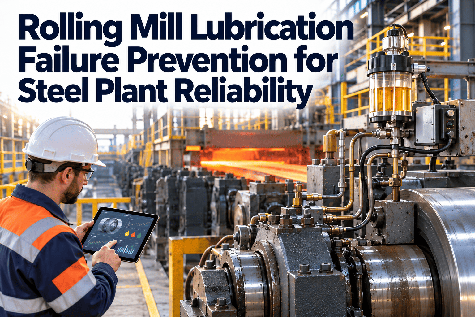
In a steel plant, almost every rotating, sliding, and oscillating component depends on a thin film of lubricant to survive its operating environment. Rolling mill work roll chocks experiencing radial loads of 20,000 kN. Continuous caster withdrawal and straightening rolls cycling through water spray, scale, and thermal shock simultaneously. Blast furnace bell drives operating in dusty, high-temperature environments without access for months at a time. EAF electrode arms moving under electromagnetic forces against a backdrop of radiant heat and metallic spatter. Each of these systems fails — bearing seizure, gear tooth fatigue, hydraulic seal damage, wear-accelerated dimensional loss — when lubrication is wrong. Wrong lubricant type, wrong viscosity, wrong relubrication interval, wrong quantity, wrong application method, or simply lubricant that has degraded before it was changed. The consequence is not just a maintenance cost — it is a production cost. A single bearing failure on a rolling mill backup roll costs £150,000–£400,000 in parts and lost production. A lubrication program that prevents that failure pays for itself many times over. Yet lubrication management in steel plants is consistently underfunded, understaffed, and underpowered as a maintenance discipline relative to its contribution to equipment reliability. Schedule a free lubrication program assessment with our team and find out exactly where your current program is leaving reliability and cost performance on the table.
Why Lubrication Fails in Steel Plant Environments
Steel plant lubrication faces challenges that do not exist in any other industrial environment simultaneously. The combination of extreme loads, extreme temperatures, water contamination, metallic particle contamination, and long relubrication intervals creates conditions that defeat lubricant performance in ways that are specific to each application and cannot be resolved by generic industrial lubrication programs.
01
Contamination — The Number One Cause of Premature Bearing Failure
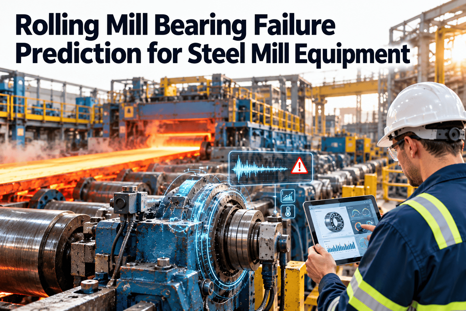
Solid particle contamination — mill scale, metallic debris, refractory fines — accelerates bearing fatigue by a factor of 3–10× compared to clean lubricant operation. In rolling mills, scale penetrates bearing seals despite the best available seal designs. Water contamination from cooling water systems reduces lubricant viscosity, promotes corrosion, and enables microbial growth in circulation systems. A contamination management program is not optional — it is the foundation of every other lubrication activity.
02
Incorrect Relubrication Intervals — Too Long and Too Short Both Cause Failure
Fixed-time relubrication intervals set for worst-case conditions result in over-lubrication for most equipment most of the time — flooding bearings with excess grease that generates heat, and wasting lubricant on equipment that does not yet need it. Under-lubrication of high-cycle equipment between maintenance visits causes film breakdown and accelerated wear. The correct relubrication interval is based on actual bearing operating conditions, not manufacturer defaults, and it varies by season, production rate, and equipment condition.
03
Wrong Lubricant Selection — Viscosity and Additive Mismatches
Steel plant equipment operates across a temperature range from -20°C ambient in winter to 200°C+ bearing operating temperatures in hot rolling mills. A grease that performs correctly at 80°C operating temperature may be too thick to penetrate bearing clearances at a cold start in winter — causing wear during the most vulnerable period of the operating cycle. Lubricant selection that accounts for the actual operating temperature range, load, speed, and contamination environment for each application is the foundation of lubricant specification management.
04
Automatic Lubrication System Failures — Silent and Dangerous
Centralised automatic lubrication systems serving dozens of bearing points on a single machine can fail silently — a blocked distribution line, a failed progressive divider valve, or an empty reservoir that triggers no alarm means every downstream bearing is being starved while operators assume the system is running correctly. Automatic lubrication system maintenance and monitoring is a programme requirement in its own right, not an afterthought.
36%
Of all premature bearing failures in steel plants attributed to inadequate lubrication — the single largest preventable failure category
3–10×
Bearing fatigue life reduction from ISO cleanliness code 22 (typical field condition) versus ISO 16 (clean system target)
£150K–£400K
Cost of a single rolling mill backup roll bearing failure — parts, crane time, and production loss combined
4–8×
Return on investment documented from structured steel plant lubrication programs versus unmanaged lubrication spend
Lubrication Requirements by Steel Plant Equipment Area
Each major equipment area in a steel plant has distinct lubrication requirements driven by its specific combination of load, speed, temperature, contamination exposure, and access constraints. Generic lubrication programs fail because they treat fundamentally different applications with the same approach.
Rolling Mills
Highest Lubrication Criticality
Work Roll and Backup Roll Chocks
High EP grease — ISO VG 460–680 base oil viscosity, extreme pressure additives, high water resistance. Relubrication at every roll change plus condition-based monitoring via oil analysis on circulating systems. Critical: contamination exclusion via labyrinth seals and positive pressure air purge.
Main Drive Gearboxes
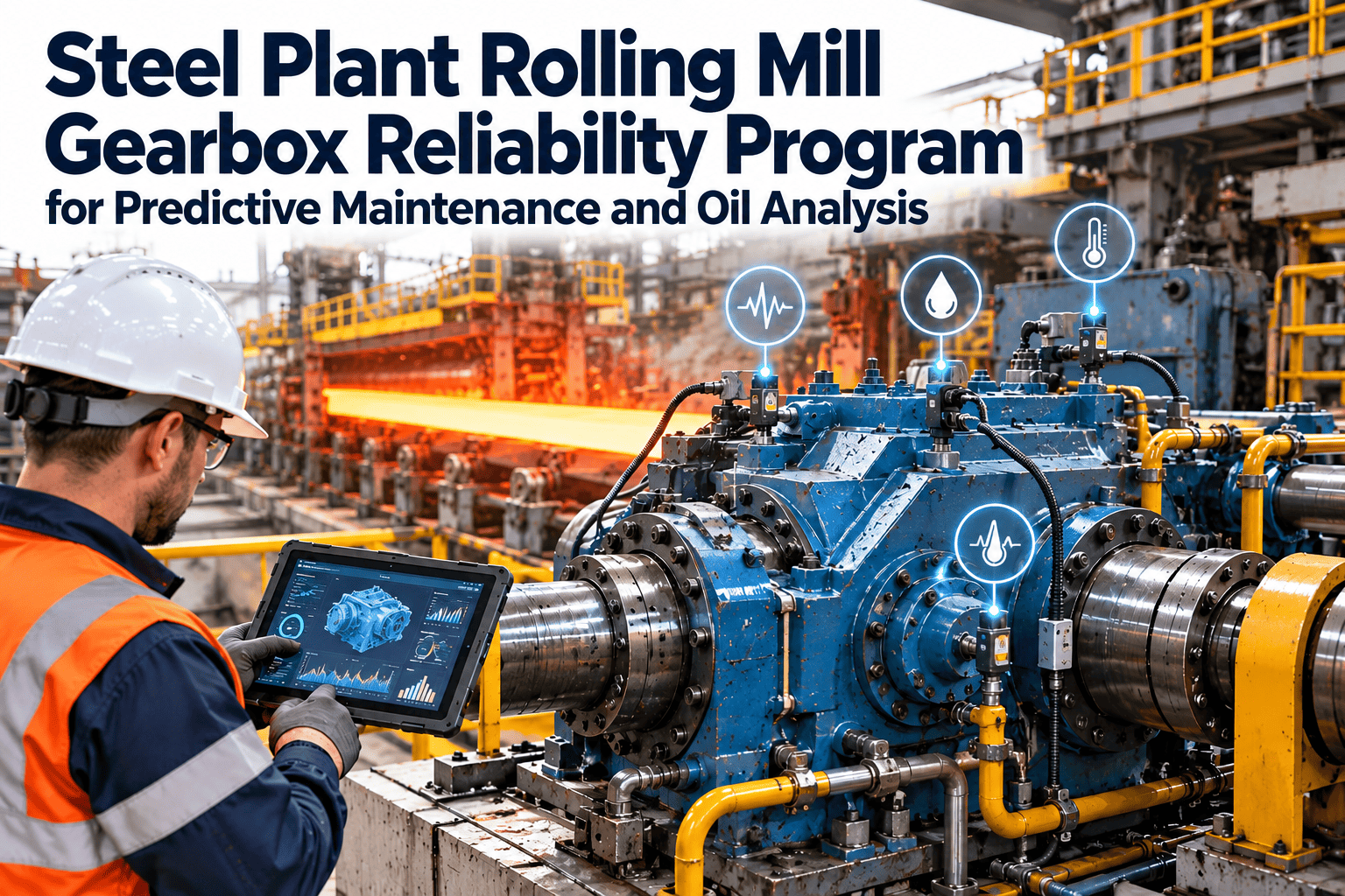
Circulating mineral oil — ISO VG 220–460 depending on gear design. Continuous filtration to ISO 16/14/11. Oil analysis monthly for viscosity, water, metals, and additive depletion. Temperature monitoring continuous.
Roll Bending and Shifting Hydraulics
HM hydraulic oil ISO VG 46 — servo circuits require ISO 16/14/11 cleanliness or better. Heat exchanger performance monitoring. Quarterly oil sampling minimum.
Continuous Casting
Extreme Environment
Segment Roller Bearings
High-temperature, water-resistant lithium complex or calcium sulfonate grease. Centralized automatic lubrication systems with individual line monitoring. Relubrication cycles driven by strand throughput (tonnes cast), not time. Critical: water contamination exclusion.
Mold Oscillation Drive
Grease lubricated eccentric and bearing assemblies with short relubrication intervals driven by stroke frequency. Vibration monitoring detects bearing degradation before it causes oscillation quality problems. Stroke frequency × time = relubrication trigger.
Withdrawal and Straightening Unit
Roll neck bearings under combined radial and axial loading in high-temperature environment. High-temperature grease minimum drop point 250°C. Automatic lubrication with manual inspection confirmation.
Reheat Furnaces and EAF
High Temperature Specialist
Furnace Pusher and Walking Beam Drives
Open gear compounds for rack and pinion systems. High-temperature grease for pivot bearings operating above 150°C ambient. Access constraints mean relubrication must be planned precisely — missed intervals cause rapid wear at these cycle rates.
EAF Electrode Arm Pivots
Extreme-pressure, high-temperature grease under electromagnetic vibration loading. Contamination from metallic spatter and carbon fines requires sealed housings and positive pressure protection.
Material Handling and Transport
High Volume, Lower Criticality Per Unit
Conveyor Drive Gearboxes and Bearings
Standard EP gear oil for gearboxes — ISO VG 220. Pillow block and flanged bearing greasing on annual-to-quarterly cycles depending on ambient temperature and duty cycle. Automatic lubrication cost-justified on high-point-count systems.
Ladle and Scrap Car Wheels and Axles
High-temperature open gear paste or grease for wheel flanges and axle bearings exposed to radiant heat and mechanical shock loading from track impacts.
Schedule Every Lubrication Task. Track Every Application. Never Miss a Critical Interval.
Oxmaint gives steel plant lubrication teams a digital maintenance platform that schedules all lubrication tasks, confirms completion with photo evidence, tracks oil analysis results, monitors auto-lube system performance, and generates the lubrication program compliance records that audit teams require.
Oil Analysis: The Diagnostic Engine of a Predictive Lubrication Program
Used oil analysis is the most cost-effective condition monitoring tool available for steel plant lubrication management. A sample costing £15–£40 to analyse can detect bearing wear, lubricant degradation, contamination ingress, and additive depletion — providing 4–8 weeks of advance warning before the failure that would cost hundreds of thousands of pounds. Yet oil analysis programs in most steel plants are incomplete, inconsistently executed, or disconnected from the maintenance action they are designed to trigger.
Viscosity
Every sample
The most fundamental oil property. Viscosity change indicates thermal degradation (decrease), contamination with water or lighter oil (decrease), or oxidation and varnish formation (increase). Either direction of change affects film strength.
Caution: ±10% from new oil specification
Action: ±20% — immediate oil change required
Wear Metals (ICP)
Every sample
Iron, chromium, and manganese indicate bearing wear. Copper and tin indicate bronze cage or bushing wear. Silicon indicates dirt ingression. Each metal source in the oil maps to a specific component — trend analysis identifies which specific component is wearing before failure occurs.
Caution: Rising trend above baseline regardless of absolute value
Action: Concentration doubles from previous sample — investigate immediately
Water Content (KF)
Every sample — priority in caster and hot mill
Water in circulation oil above 0.05% causes accelerated oxidation, additive hydrolysis, microbial growth in recirculation tanks, and emulsification that prevents film formation. Water contamination in rolling mill bearing oil systems is the most common cause of accelerated bearing fatigue in that environment.
Caution: > 0.05% (500 PPM) in gearboxes
Action: > 0.1% — oil change and source investigation
Particle Count (ISO 4406)
Every sample on circulating systems
The cleanliness code directly determines bearing fatigue life. A one-ISO-code increase in particle count reduces bearing life by approximately 30%. Particle counting on recirculating systems identifies filter performance degradation and ingression events before they cause measurable wear metal increases.
Target: ISO 16/14/11 on servo systems
Action: Two codes worse than target — flush and filter investigation
Additive Depletion (FTIR/RULER)
Quarterly on major circulating systems
Antioxidant, anti-wear, and extreme-pressure additive depletion determines remaining useful lubricant life. FTIR (Fourier Transform Infrared) detects oxidation products and additive consumption. RULER (Remaining Useful Life Evaluation Routine) quantifies antioxidant percentage remaining — the most reliable oil change trigger for premium circulating oils.
Caution: Antioxidant below 50% of new oil value
Action: Below 25% — schedule oil change within 4 weeks
Ferrography (Particle Morphology)
On-condition — when wear metals elevated
Analytical ferrography examines the size, shape, and surface texture of wear particles under magnification to identify the specific wear mechanism — sliding wear, rolling fatigue, abrasive wear, or adhesive wear. When ICP shows elevated iron but the failure mode and location are uncertain, ferrography provides the diagnostic specificity that guides the right corrective action.
Triggered: When ICP wear metals rise without obvious cause
Centralised automatic lubrication systems (CALS) — progressive divider systems, dual-line grease systems, and oil mist systems — are the only practical solution for the large bearing point counts on rolling mills, casters, and material handling equipment in steel plants. They are also among the most maintenance-neglected systems in the plant, because when they fail, the failure is silent — no alarm, no visible indication — until the bearing fails.
Progressive Divider Systems
Used on: Rolling mill roll necks, conveyor bearings
Progressive divider valves distribute grease sequentially to each bearing point — each downstream valve must operate before the next activates. A single blocked or seized bearing point stops all downstream lubrication. End-of-line movement indicators or cycle switches confirm system operation per lubrication cycle.
!Blocked distribution lines — scale and debris ingress at bearing point fittings
!Seized valve piston — grease starvation to all downstream points silently
!Line fractures — grease loss to ground without reaching bearing
Dual-Line Grease Systems
Used on: Caster segments, large bearing populations
Two main lines alternately pressurised via a reversing valve distribute grease to each bearing point through metering valves. More robust than progressive systems — a single bearing point blockage does not affect others. Pressure monitoring on each main line detects line failures and pump performance degradation.
!Metering valve wear — inconsistent or zero delivery per cycle
!Reversing valve failure — one line pressure never built, half the system starved
!Reservoir empty without alarm — all bearing points in starvation simultaneously
Minimum Monitoring Requirements for ALS Systems in Steel Plants
✓
Reservoir level sensor with low-level alarm — minimum 24-hour warning before empty at maximum consumption rate
✓
Cycle counter or end-of-line indicator on each progressive divider circuit — confirms grease reached the furthest bearing point
✓
Main line pressure monitoring on dual-line systems — pressure build-up time trending detects pump degradation before failure
✓
Scheduled manual confirmation inspections — all system indicators checked and recorded per shift on critical systems
✓
Lubricant compatibility verification at every refill — wrong grease type added to a centralised system can contaminate all bearing points
Lubrication Program KPIs for Steel Plants
A steel plant lubrication program without measurable KPIs is a program without accountability. These metrics provide the evidence base for demonstrating program effectiveness, identifying where improvements are needed, and justifying continued investment in lubrication as a reliability discipline.
100%
Lubrication Task Completion Rate
All scheduled lubrication tasks completed on time. Missed lubrication events on critical equipment are a leading indicator of future bearing failures — tracked per equipment area to identify systematic gaps in coverage.
< 5%
Oil Analysis Abnormal Sample Rate
Percentage of oil samples returning caution or action results — sustained above 15% indicates systematic program issues. Below 5% demonstrates consistent lubricant management. Trending per equipment area identifies the worst-performing systems for targeted improvement.
4–8×
Target ROI on Lubrication Program Investment
Return on lubrication program spend measured as (bearing failures prevented × average failure cost) / (lubrication program cost). Well-structured steel plant lubrication programs consistently document 4–8× ROI against baseline reactive lubrication spend. Below 2× indicates program gaps requiring systematic review.
Bearing MTBF by Equipment Area
Increasing trend
Mean time between bearing failures tracked per major equipment group — rising MTBF confirms lubrication program improvements are translating into equipment reliability gains
Oil Analysis Sample Coverage
100% per schedule
Percentage of scheduled oil samples taken on time — missed samples create monitoring gaps that allow undetected degradation and contamination to progress toward failure
Lubrication-Related Failure Rate
Declining trend
Bearing and gear failures attributed to lubrication causes per quarter — the ultimate program effectiveness indicator that connects lubrication activities directly to production reliability outcomes
ALS System Availability
> 99%
Percentage of operating hours during which each automatic lubrication system is confirmed operational — ALS downtime creates bearing starvation on every point it serves simultaneously
A Lubrication Program Is Only as Good as the System Tracking It
Oxmaint schedules all lubrication tasks to the right technician at the right interval, captures completion with digital confirmation in the field, tracks oil analysis results with trend alerts, monitors ALS system status, and gives maintenance managers the real-time visibility they need to run a program that actually protects equipment — not just generates paperwork.
Common Lubrication Program Failures in Steel Plants
01
No Formal Lubricant Specification Register
Most steel plants operate with 30–80 different lubricants across all equipment areas — mineral oils, synthetic oils, greases, open gear compounds, hydraulic fluids, and specialty products. Without a documented specification register that maps every lubrication point to the correct lubricant, grade, quantity, and application method, substitutions happen silently — correct viscosity substituted with wrong additive type, EP grease used where anti-wear grease is specified, incompatible greases mixed in bearing housings. The specification register is document zero of any lubrication program.
Consequence: Incompatible lubricants accelerate wear at a rate indistinguishable from contamination failure — root cause missed without specification records
02
Oil Analysis Without Action Protocol
Many steel plants run oil analysis programs that generate reports that sit unread in email inboxes or paper files. Without a defined action protocol — who reviews each report, what actions each result level triggers, who is responsible for ensuring the action is completed, and how completion is verified — oil analysis is an expense that generates data without delivering value. The analysis is not the program — the management of the analytical output is the program.
Consequence: Equipment fails on the same machines that recently returned abnormal oil analysis results — the program existed but the warning was not acted upon
03
Relubrication Quantities Not Matched to Bearing Size
The correct grease relubrication quantity for a bearing is calculated from the bearing bore diameter and width — not from how much comes out of the grease gun before resistance is felt. Over-greasing generates heat from churning, increases seal pressure causing seal failure, and pushes old contaminated grease further into the bearing rather than out of the purge path. Under-greasing leaves areas of the bearing raceway unprotected. Both conditions cause premature failure — and both are caused by technicians who have never been given the correct quantity specification for each bearing point.
Consequence: Bearing failures attributed to "grease failure" that are actually failures of grease quantity management — never diagnosed correctly without documented specifications
04
Lubricant Storage and Handling Without Contamination Control
New oil as delivered by suppliers contains particulate contamination at levels that would immediately damage precision steel plant bearings and servo valves. Drums stored outdoors experience condensation contamination through the bung. Grease guns transfer contamination from the nozzle to the bearing fitting if the fitting is not cleaned before connection. A contamination ingression prevention program — covering storage, dispensing equipment, and application procedures — must be part of the lubrication program documentation.
Consequence: "New oil" added to clean systems introduces the contamination that then causes the bearing failure attributed to the oil supplier's product quality
Frequently Asked Questions
01
How often should oil analysis be performed on rolling mill gearbox oil?
Rolling mill main drive gearboxes should be sampled monthly under active production conditions. The rationale is that a rolling mill gearbox failure is a production-stopping event costing £300,000–£800,000, the oil analysis sample costs £20–£40, and the monthly sampling frequency gives enough data points to detect wear metal trends before they reach critical levels. Sampling less frequently than monthly means that a developing fault — a bearing beginning to shed fatigue spalls, for example — can escalate from "early warning" to "imminent failure" between samples without an opportunity for planned intervention. The sample should always be taken from a live system under operating temperature, from the same sampling point on every occasion, and sent to the laboratory within 48 hours of collection for accurate results. Each result should be trended against the previous 6–12 months of results for that specific gearbox, not evaluated in isolation against limits alone — a rising trend matters even if the current absolute value is still within limits.
02
What is the correct approach to specifying grease relubrication intervals for continuous caster bearings?
Continuous caster bearing relubrication intervals should be based on strand throughput — tonnes cast or metres of strand produced — rather than calendar time, because the actual bearing operating time and thermal loading are directly proportional to production volume rather than elapsed time. The calculation starting point is the SKF or equivalent manufacturer's formula for grease relubrication frequency based on bearing bore diameter, speed factor (ndm), and operating temperature. This calculated base interval is then modified for the specific caster environment: derated by 50% for water spray contamination exposure, further derated for segment roll bearings operating above 120°C, and adjusted for the specific grease type being used (calcium sulfonate complex greases have longer intervals than lithium complex at equivalent temperatures). The resulting interval should be validated against bearing condition evidence — if segment roll bearings consistently show corrosion pitting or water-contaminated grease at change-out, the interval is too long or the grease specification is inadequate for the water ingress condition. A lubrication FMEA (Failure Mode and Effects Analysis) for each caster bearing type is the systematic tool for arriving at the correct specification, and it should be reviewed every 2–3 years as operating conditions and grease product technology evolve.
03
How does a CMMS improve steel plant lubrication program management?
A maintenance management system provides the scheduling, tracking, and analytical infrastructure that converts a lubrication specification document into an operational program with measurable outcomes. It schedules every lubrication task — from individual bearing point greasing to gearbox oil sampling to ALS system inspection — with the correct frequency, assigned to the right technician, with the correct lubricant specification, quantity, and application method accessible in the field. It confirms task completion with digital sign-off and, where required, photographic evidence — creating the audit trail that demonstrates to equipment owners and management that the program is actually being executed rather than just scheduled. It receives oil analysis results and integrates them with the equipment maintenance record, automatically flagging abnormal results for engineer review and generating follow-up work orders when action levels are reached. It tracks the lubrication-related component history for each asset — every grease application, every oil change, every ALS system repair — in a format that enables trend analysis correlating lubrication interventions with bearing failure rates. And it provides the programme-level reporting — task completion rates, abnormal sample rates, lubrication-related failure trends — that allows lubrication program managers to demonstrate value and identify improvement opportunities with actual data.
04
What are the highest-priority lubrication improvements for a steel plant starting to formalise its lubrication program?
For a steel plant beginning to formalise its lubrication program from a reactive baseline, the three highest-impact initial actions are: first, create a complete lubricant specification register mapping every major bearing point and circulating system to the correct lubricant, grade, quantity, and interval — this document eliminates the specification errors and substitutions that cause failures without generating any diagnostic data trail; second, implement oil analysis with a defined action protocol on the top 10–15 circulating oil systems by failure consequence — rolling mill main drives, caster segment circulation, hydraulic systems for critical production equipment — and ensure the protocol specifies who reviews each report within 48 hours of receipt and what action each result level triggers; third, audit all automatic lubrication systems against their specifications — confirm all reservoir levels, all cycle indicators are functioning, and all distribution lines are intact — and establish a documented weekly ALS inspection round. These three actions alone, consistently executed, will deliver measurable bearing failure rate reduction within 6–12 months at minimal capital cost. The lubrication specification register is the foundation on which all other program elements depend — it is also the element most consistently absent in plants with poor lubrication outcomes.