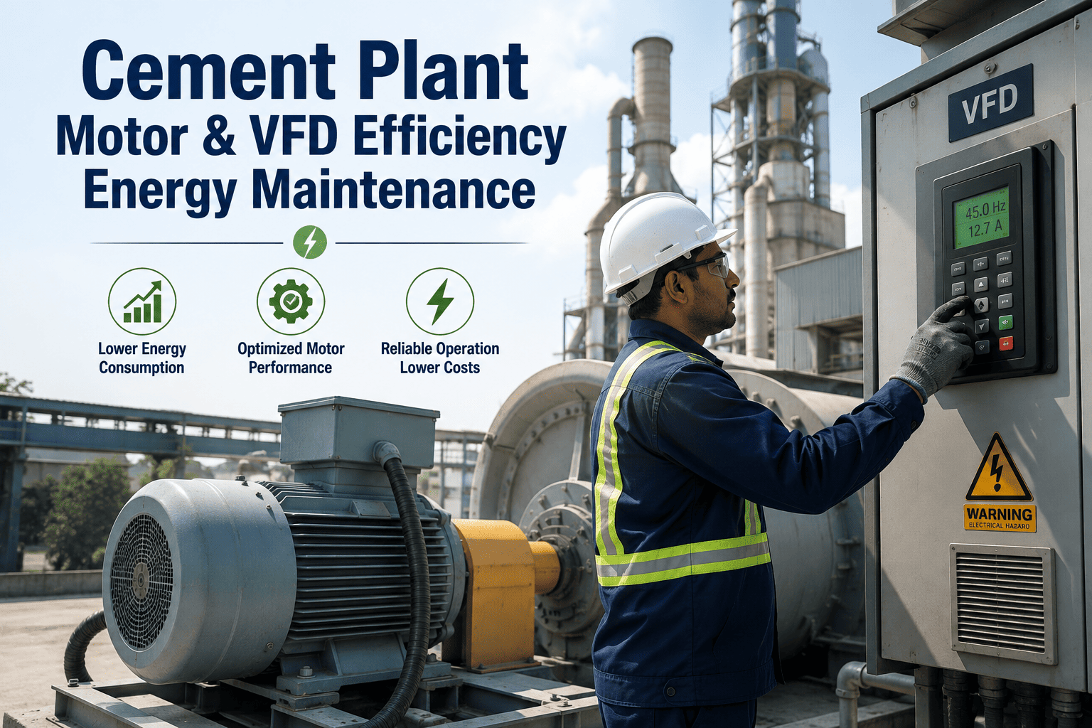
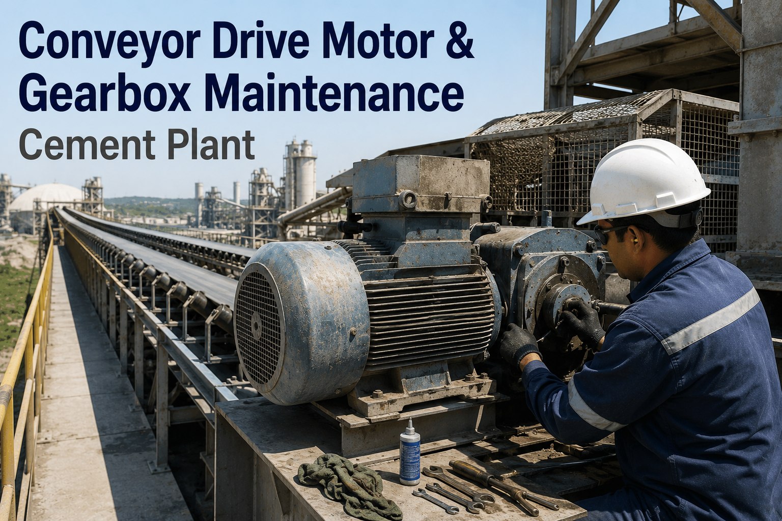
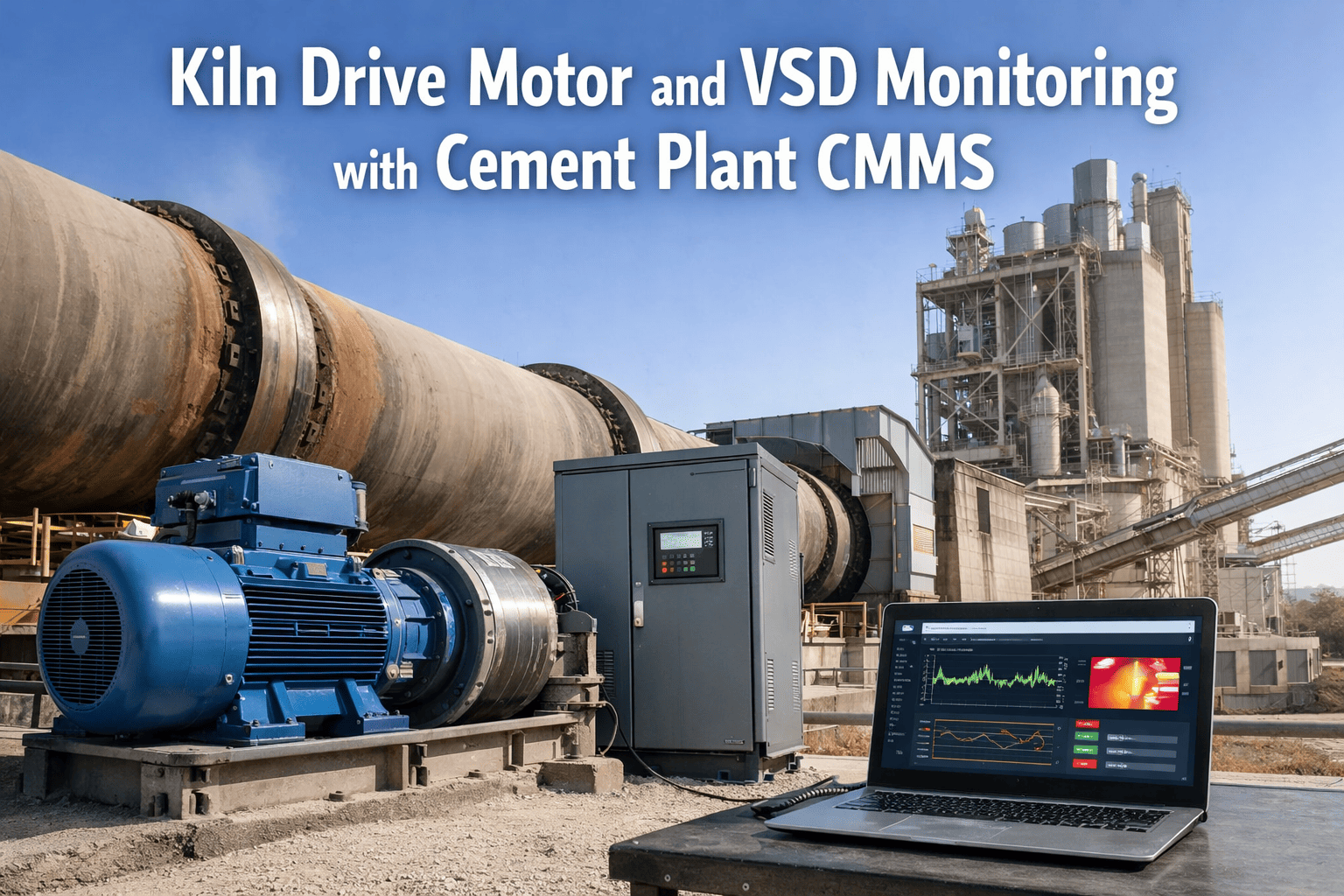
Electricity accounts for 30% of total cement manufacturing costs, and grinding operations alone consume up to 70% of a plant's entire electrical load. Yet across the global cement sector, energy efficiency has improved only 18% since 1990 — a gap that represents hundreds of thousands of dollars in recoverable savings at every facility. Variable frequency drives close that gap faster than almost any other single investment. The physics is straightforward: reducing motor speed by just 20% cuts power consumption by up to 50% thanks to the cubic relationship governed by the Affinity Laws. A China-based cement plant deploying VFDs across its kiln exhaust fans reduced specific energy consumption by 10%, generating $124,000 in annual savings. Holcim's Ste. Genevieve facility — the largest single kiln line plant in North America — achieved EPA ENERGY STAR certification for super energy efficiency two consecutive years, crediting VFD technology as a core enabler. European field data confirms that VFD-equipped fans deliver payback measured in months, not years. If your plant still runs high-power motors at full speed with damper-based flow control, you are burning money on every rotation. Start tracking your motor assets with Oxmaint and build the data foundation for a smarter energy strategy.
How Variable Frequency Drives Work in Cement Plants
A variable frequency drive is an electronic power controller that regulates the speed and torque of AC electric motors by adjusting the frequency and voltage of the power supply. In a cement plant, motors drive every critical process — from raw material crushing and grinding to kiln rotation, fan systems, and finished cement conveying. Without VFDs, these motors run at full speed regardless of actual process demand. Operators use mechanical devices like dampers, louvers, guide vanes, and throttling valves to restrict output — a method that wastes enormous energy by converting motor power into heat and friction rather than useful work.
Rectifier Stage
Converts incoming AC power to DC. This intermediate DC bus provides the stable power foundation for precise frequency generation.
Inverter Stage
Converts DC back to AC at precisely controlled frequency and voltage. This variable output directly determines motor speed.
Motor Speed Control
Motor speed tracks the output frequency. Process control systems feed demand signals to the VFD, which adjusts speed in real time to match actual load.
Reduce speed by 20% and flow drops by 20% — a linear relationship.
That same 20% speed reduction cuts pressure by 36% — a squared relationship.
Power consumption drops by 48.8% — the cubic law that makes VFDs so effective on fan and pump loads.
Key VFD Applications Across the Cement Process
VFDs deliver value at nearly every motor-driven stage of cement production. The highest-impact applications target high-power equipment with variable load profiles — particularly fans, blowers, pumps, and grinding mills. Each application has distinct engineering requirements and savings potential. Tracking VFD-equipped motor health, runtime, and energy consumption requires a structured asset management system — sign up for Oxmaint to centralize your motor and drive maintenance program.
Track Every VFD-Equipped Motor in One Platform
Oxmaint centralizes motor runtime data, VFD fault logs, PM schedules, and energy baselines — giving your electrical and maintenance teams a single source of truth for drive-equipped assets across the plant.
Energy Savings Breakdown: Before vs. After VFD Installation
The economic case for VFDs is driven by the cubic power-speed relationship. Real-world cement plant data consistently shows savings that outperform theoretical projections because VFDs also improve process stability, reduce mechanical maintenance, and improve power factor — benefits that compound over the asset lifecycle.
VFD Maintenance Requirements in Cement Environments
Cement plants present uniquely hostile conditions for electronic equipment: fine calcium carbonate dust, high ambient temperatures near kiln zones, harmonic-rich power distribution systems, and continuous 24/7 operation with minimal shutdown windows. VFDs require specific maintenance attention to perform reliably in these conditions. Without structured preventive maintenance, drive failures cause the same costly unplanned downtime that the VFD investment was meant to prevent. A CMMS like Oxmaint automates VFD PM scheduling, tracks fault history, and generates condition-based alerts before failures occur.
Cooling System Inspection
VFD heat sinks and cooling fans accumulate cement dust rapidly. Blocked airflow causes thermal shutdown — the number one failure mode in cement environments. Clean heat sinks monthly; replace cooling fans every 3–5 years based on runtime hours.
Frequency: MonthlyDC Bus Capacitor Health Check
Electrolytic capacitors in the DC bus are the life-limiting component in any VFD. Capacitance degrades with heat and age, causing DC bus ripple and eventual drive trip. Measure capacitance and ESR annually; plan replacement at 7–10 year intervals.
Frequency: AnnuallyPower Quality & Harmonic Analysis
VFDs generate harmonics that can distort plant power quality, affecting other equipment and triggering utility penalties. Conduct harmonic surveys semi-annually; verify input filters and line reactors are functioning. THD should remain below 5% at PCC.
Frequency: Semi-AnnualConnection Torque Verification
Thermal cycling from motor load variations loosens power terminal connections over time. Loose connections create arcing, heat damage, and intermittent faults. Retorque all power and control connections during scheduled shutdowns.
Frequency: QuarterlyFirmware & Parameter Backup
Maintain documented backups of all VFD parameter settings. After any process optimization or retuning, update the backup immediately. A drive replacement without parameter backup can take 8–16 hours to recommission versus 30 minutes with a stored configuration.
Frequency: After each changeROI Calculation Framework for Cement Plant VFD Projects
Justifying VFD investment requires quantifying savings across multiple value streams — not just direct energy reduction. The strongest business cases include mechanical maintenance savings, extended motor life, improved power factor, and reduced process variability. Here is the framework used by plants that consistently secure capital approval for drive retrofits.
Direct Energy Savings (70–80% of Total ROI)
Calculate using: Annual kWh Saved = Rated kW × Hours × (1 - (New Speed / Rated Speed)³). For a 1,000 HP ID fan running 8,000 hrs/yr at average 80% speed, savings exceed 350,000 kWh annually. At $0.10/kWh, that is $35,000/year from a single motor.
Mechanical Maintenance Reduction (10–15% of ROI)
Eliminating dampers, louvers, guide vanes, and slip clutches removes mechanical wear points. Soft-start capability reduces motor starting stress — lowering bearing failures, coupling replacements, and gearbox maintenance by 15–25%.
Power Factor Improvement (5–10% of ROI)
VFDs inherently correct power factor to 0.95–0.99 on the input side. For plants paying utility penalties below PF 0.85, this alone can save $10,000–$50,000 annually depending on load and rate structure.
Extended Equipment Life (Hidden Value)
Reduced mechanical stress extends motor bearing life by 2–3x. Soft start eliminates inrush current (6–8x FLA down to 1–1.5x), removing thermal cycling stress from motor windings and reducing rewinding frequency. VFD reliability exceeds 99.999% availability when properly maintained.
Build Your VFD Business Case with Real Asset Data
Oxmaint tracks motor runtime hours, energy baselines, fault histories, and maintenance costs — giving you the documented evidence to justify VFD investment and measure actual post-installation savings.
Implementation Best Practices for Cement Plants
VFD installations in cement plants fail not because of drive technology limitations but because of poor site assessment, inadequate power quality analysis, or insufficient environmental protection. Follow these engineering best practices to ensure your VFD deployment delivers its full savings potential from day one.
Conduct Detailed Load Profiling Before Purchase
Install temporary power loggers on target motors for a minimum of 30 days covering all operating scenarios. Capture actual speed requirements, load variations, and duty cycles. Many fan applications run at 60–80% demand for 70%+ of operating hours — this data is what turns a theoretical savings estimate into a bankable number. Do not rely on nameplate data alone.
Specify Cement-Grade Enclosures and Filtration
Standard NEMA 1 enclosures are insufficient for cement plant environments. Specify NEMA 12 or IP54 minimum with positive-pressure filtered cooling or air-to-air heat exchangers for drives near kiln zones. Conformal coating on PCBs provides additional protection against conductive dust contamination. Budget 10–15% extra for proper environmental protection — it is the difference between 15 years of service and 3 years of failures.
Address Harmonic Mitigation at Design Stage
Six-pulse VFDs generate 5th and 7th harmonics that can exceed IEEE 519 limits when multiple drives share a bus. For installations above 500 HP, evaluate 12-pulse or 18-pulse front-end configurations, or specify active front-end (AFE) drives that regenerate clean power. Install line reactors on all drives below 500 HP. Total harmonic distortion at the point of common coupling must remain below 5%.
Plan for Bypass Capability on Critical Fans
For kiln ID fans and other process-critical applications, install a bypass contactor arrangement that allows the motor to run across-the-line if the VFD fails. This prevents an entire kiln shutdown during a drive fault. The bypass should include soft-start capability or reduced-voltage starting to limit inrush. Document the bypass procedure as a standard work order in your CMMS.
Integrate VFD Data into Plant Control and CMMS
Modern VFDs output rich diagnostic data via Modbus, Profibus, or Ethernet/IP — motor current, speed, torque, DC bus voltage, heat sink temperature, fault codes, and accumulated energy. Feed this data into your DCS for process optimization and into Oxmaint for predictive maintenance triggering. A VFD reporting elevated heat sink temperature is a maintenance work order waiting to happen — automate that connection.
Frequently Asked Questions
How much energy can VFDs actually save in a cement plant?
Real-world savings range from 10–45% depending on the application. Fan and blower applications with variable demand profiles see the highest returns (25–45%) due to the cubic power-speed relationship. Mill drives and conveyors typically achieve 10–25%. A comprehensive VFD program across all major motors can reduce total plant electrical consumption by 15–20%, translating to hundreds of thousands of dollars in annual savings for a mid-size cement facility.
What is the typical payback period for a VFD installation?
For fan and blower applications, payback typically falls between 8–18 months. Mill drive applications have longer payback at 18–30 months due to higher drive costs and lower percentage savings. European cement sector field data shows VFD-equipped fans deliver payback measured in months rather than years. Including maintenance savings, power factor correction, and reduced mechanical wear shortens the ROI timeline further.
Can existing motors be retrofitted with VFDs?
Yes, most standard induction motors can be retrofitted. However, motors designed for constant speed may need additional considerations: insulation class should be verified for inverter duty (the fast switching creates voltage spikes), bearings may need shaft grounding rings to prevent electrical discharge damage, and cooling at low speeds may require a separate blower. For motors above 15 years old, it often makes sense to replace the motor with an IE3 or IE4 inverter-duty unit simultaneously.
Do VFDs create harmonic problems on the plant electrical system?
Standard six-pulse VFDs do generate harmonics — primarily 5th and 7th order. This is manageable with line reactors on smaller drives and multi-pulse configurations on larger ones. IEEE 519 compliance requires total harmonic distortion below 5% at the point of common coupling. Modern active front-end drives virtually eliminate harmonics but cost 20–30% more. A harmonic study should be conducted before any installation above 500 HP.
How does dust affect VFD reliability in cement plants?
Cement dust is the primary environmental threat to VFD reliability. Fine calcium carbonate particles are conductive when combined with moisture, causing tracking across PCB surfaces and eventually short circuits. Proper enclosures (NEMA 12 or IP54 minimum), filtered positive-pressure cooling, and monthly heat sink cleaning are essential. Plants that follow these practices routinely achieve 15+ year VFD service life. Those that skip environmental protection see failures in 2–4 years.
Should we use low-voltage or medium-voltage VFDs?
For motors below 500 HP, low-voltage (480V) VFDs are standard and cost-effective. For motors above 500 HP, medium-voltage drives (2.3–6.6 kV) are preferred because they eliminate the need for step-down transformers, reduce cable sizes, and handle the high currents more efficiently. Many cement plants have motors in the 2,000–6,000 HP range for mills and major fans — these almost always justify medium-voltage drive solutions.
How does a CMMS help manage VFD maintenance?
A CMMS tracks VFD-specific PM tasks (cooling system cleaning, capacitor testing, connection torque checks, firmware backups), logs fault history and diagnostic data, manages spare parts inventory (capacitors, fans, fuses, IGBTs), and triggers condition-based maintenance when drive parameters exceed thresholds. Without a CMMS, VFD maintenance is typically reactive — teams only respond after a drive trips and production stops. Structured preventive maintenance extends VFD life from 5 years to 15+ years.
Related Resources for Cement Plant Optimization
Cement Kiln Energy Optimization & Fuel Consumption
Thermal efficiency strategies, heat balance calculations, and fuel benchmarking for rotary kiln systems.
Read Full Guide →Reduce Unplanned Downtime in Cement Plants with CMMS
How leading operations cut unplanned stops by 45% and drive kiln availability above 92%.
Read Full Guide →Cement Production Efficiency & KPI Tracking
Essential KPIs, dashboard design, and data-driven decision frameworks for cement plant performance.
Read Full Guide →Cement Ball Mill Maintenance & Troubleshooting
Wear patterns, liner management, lubrication protocols, and grinding optimization techniques.
Read Full Guide →